1. HISTORY OF VERSIONS
After
several years of development (preliminary version in 2005), Laboratori
d'envol presents in 2010 "LEparagliding 1.0" paraglider design program,
that follow the
laboratory concepts and techniques, and allows improved design for the
new
gliders. With
the help of LEparagliding 1.0
has been possible to design the gnuLAB2 paraglider in
2010.
The latest version released is LEparagliding 3.23 (January 2025), which contains many enhancements over the previous
versions.
2.00:
- Scale factor to design different
sizes
- Elastic
corrections in
the lines, depending on
the load
- Plans
prepared for printing on
paper (amateur use)
or for computer cutting table (professional
use).
- Design aids to facilitate the
work of sewing
- Support for the division of the sail panels in colors (testing)
- Horizontal straps
- V-ribs
(two cells without lines)
- VH-ribs
(three cells without lines, in testing)
- Rotation
of triangles in space for
single surface paragliders (choice of double "ds" or simple surface "ss" paraglider! in testing). BHL paragliders design.
- In
general, better presentation of the plans, although there is
still much room for improvement
- 2D steering allowed (two or more main brake lines)
2.33:
- Improvements in the shape of single skin sawtooth profiles
- lines.txt human-readable list of lines
- new type of wing "pc", special for parachute design
2.35:
- Eighth column, in section 2, is now used in single paragliders (useless in double skin). More control in rotation of triangles.
- Other minor corrections
2.40 (2015-09-04):
 LEparagliding 2.40 using "full continous diagonal rib"
- Distance between equidistant points of control seam at the bottom of the profiles, improved (fixed a bug). Thanks to Scott from Utah - USA.
-
Few improvements in the drawing number 6 of 2D drawings "Calage
estimation". The calculation of the angle of attack of the wing (alpha)
and angle of the airfoil chord with respect horizon (theta) or
"assiette", now is drawn correctly (fixed a bug). Thanks to Yuri from Crimea. More info in excell file: Balance_calculus.xls
- Changed executable name from a.out or a.exe to lep-2.40.out or lep-2.40.exe (optional)
- V-ribs "type 3" now possible
- V-ribs "type 5" new type "full continous diagonal rib" includes
parabolic and elliptical holes (very especial thanks to Scott for
supporting leparagliding developement)
- In lep-out.txt output file added summary of ribs and panel lenghts differences
- Preprocessor 1.2 version "Gurzuf" with more info written in the output file (area, span)
- Graphical user interface (first ideas)
2.41 (2015-09-19):
- Attachements points marks in intrados panels (Scott request).
- Increased number of ribs with color marks, from 20 to 100 (per side). (Thanks to Paweł from Poland)
- Now possible draw color marks also in intrados panels. Use same format for data that in extrados.
- Now is possible define and draw trailing edge "miniribs" ("minicabs")
in non "ss" paragliders: Simply define minirib length (in %) in column
number 8 of section "2. AIRFOILS". If column 8 values are "0" or "1",
miniribs are not draw and these values used only in "ss" paragliders,
according manual 2.41.
2.48 (2016-04-17):
- Using new reformatting option (fully adjustable) for high accuracy in length between panels and ribs,
corrections in lenght and distorsion. And many others improvements.
- Using DOUBLE PRECISION
real variables and double precision trigonometric functions in Fortran
code
- Special thanks to Scott from Utah (USA), which has made possible this new version.
- Read README.txt file for details
2.49 (2016-04-24):
- V-rib
type 6 is fully functional. Type 6 is a general diagonal. It's very
simple. A trapezoidal diagonal ranging from rib number i to rib number
i+1. But the rib is totally configurable in size and position. It has
been designed to develop competition paragliders CCC types, which need
to jump between 4 and 5 cells without lines. But it can also serve to
design simplest paragliders, and replacing some of the types of
diagonals described above. It is also very useful to define transverse
horizontal strips located in all parts of the wing (the tapes have not
necessarily coincide with the anchor points).
- In final report lep-out.txt, area and span, calculated also in ft2 and ft
- Improved location of decimal numbering of all V-ribs types.
-
Read section 10 of the manual: (...) "i11" indicates rib number "i",
where anchor the top line of the brakes. This number, usually an
integer. Nevertheless, some versions ago was added an interesting and
not documented feature. Is possible define a decimal which means the
displacement of the anchoring point between the rib "i" and the rib and
"i+1". For example, 8.4 means anchor the line in the trailing edge,
between rib 8 and 9, and 40% from the rib 8. This effect is now visible
in 2D and 3D
2.50 version "Utah" (2016-05-09)
-------------------------------------------------------------------
- Added the possibility of using "middle unloaded
ribs". Very easy to use: In section "2. AIRFOILS" at the last column
use the parameter "100", means to place a complete unloaded rib in the
middle of the panel, and the left corresponding rib. Similarly, as
defined in the mini-ribs. But the parameter "100" activates a new
specific programation. New plan numbered "1-6" with the new middle ribs
numbered and marked.
-
"Mini-ribs" are redefined, and now in section "2. AIRFOILS" at the last
column, if you use the parameter "15", means to place a 15% mini-rib in
the middle of the panel, and at the LEFT of the corresponding rib.
Previously, mini-rib it was placed on the RIGHT. But it is better set
at the left, so you can specify a minirib the center of the wing
(Mini-rib specified in the left first rib). And this is consistent with
the new middle unloaded ribs.
-
Applied little optional displacement (to the center of the wing) in the
points marking the position of the miniribs. Third parameter in the
line of section "7. MARKS" of the datafile. Before, this displacement
was set to default to zero.
- All 2D-plans renamed whit the notation "i-j" that means row "i" and column "j".
2.52 (2016-08-18)
Added new option. Set automatic washin angles from center airfoil to wingtip.
At request from Yuri (Crimea).
How to use: Below line 21 in leparagliding.txt data file:
* Alpha max and parameter
3.5 2 -1.0
- First number "3.5" is the angle of attack (degres) in wingtip airfoil
-
Second number "2" is a control parameter that means case "2", ie, add
new number indicating the angle of attack of the central airfoil
- Third number "-1.0" is the angle of attack (degres) of the central airfoil
The
distribution angles of attack is made proportional to the wing chord
(similar to case "1"). See "lep-out.txt" to view the result.
2.52++ version "Utah" (2016-08-27)
1) Added new option in V-ribs "type-3", at request from Yuri.
Diagonal rib type 3, indicated by 10 numbers.
Previously, the columns 9 and 10, were not used. And set to "0".
Now (in version 2.52++ and following), if the column 9 is set to "1", this means that the radius
defined in columns 7 "r-" and 8 "r+" , are now defined in % of the chord of the profile, not in cm.
This allows definition of the diagonals widths automatically, and proportional to the profile chord.
Thus, it is achieved a perfect match in the widths of the contiguous diagonals and chord proportionality.
2) Internal fortran subroutine "vredis" (vector redistribution) improved, because in some cases
(when used very small widths in V-ribs) were errors in the forms of V-ribs. Now fixed.
3) Version 2.52++ packs version 1.4 of the pre-processor.
2.60 version "Les Escaules" 2016-12-12
1) Corrected some problems using an even number of cells
When
we define paragliders using an even number of cells, the central
profile has a coordinate x = 0.0 along span, and program use internally
a "virtual centrall cell" with a zero thickness.
This
can cause some numerical errors when calculating angles or divisions by
zero. The result is usually an unreadable DXF file. Now, if the central
profile located at x = 0.0, the program adds internally +0.01 cm (a
tenth of a millimeter) and it seems that there are no numerical errors.
[Section 4.2 in source code file .f].
2) The
labels of the lines now automatically written on the schematic drawing
in the form of tree. This prevents errors, and had to The labels of the
lines now automatically written on the schematic drawing in the form of
tree. This prevents errors, and had to draw them
manually. :)
3) Added more geometric parameters in lep-out.txt report
2.71 (2018-06-17) to 2.99 (2019-08-24):
Since version 2.71 LEparagliding has an expanded data file structure with respect to the previous version 2.60. Sections 1 to 18 of version 2.60 are the same as those of versions greater than 2.71. But
new version has addicitonal sections numbered 19,20,21 ... up to 31. To
convert a file from version 2.60 to higher version, just add the new sections at the end of the archive leparagliding.txt. Program versions greater than 2.71 are the result of working intensively in
the source code of LEparagliding. There is a lot of invisible work in
subroutines and code improvements.
Most of the data included in the new sections can be considered as "invariant parameters", sections 19,20,24,25,28,30,31. That is, they can be used as default values for any new model. The new parameters allow for greater control of the DXF results and add some new features. Extension of the DXF-2D plans to an array 4 rows x of 7 columns (28
plans). Plan 1-7 used for rods. New plan 4-7 includes general text
notes for constructor. New sections save
a lot of drawing work with CAD, and now the paraglider is almost
finished from the program. Section 31 allows skin tension with control
of up to 100 points and applicable individually to each panel.
3.10 version "Pirineus" (2020-05-02):
Main features added in lep-3.10 over precedent version:
Data file leparagliding.txt:
Section 29. 3D-shaping active.
Section 20. Marks types, activated type8 which allows control of position and size of roman numerals
New plans added in file leparagliding.dxf:
Box (1,8) Intermediate and ovalized airfoils (*)
Box (-1,3) and (-1,5) extrados panels with 3D cuts
Box (0,3) and (0,5) intrados panels with 3D cuts
New graphics in lep-3d.dxf: intermetiade and ovalized airfoils are draw if desired.
New three informative sections added in lep-out.txt file:
Section 9. 3D internal calculus values, informative (**)
Section 10. The quotient between the lengths of the panel and ribs, for extrados and intrados.
Section 11. Counting of points in all profiles, informative
(*) Plan (1,8) shows median airfoils between rib i and i-1 and the
corresponding ovalized median airfoil, including marks of the points
j1,j2,j3,j4,j5,j6,j7 used in the defintion of the 3D-shaping.
(**) Section 9, with the length ot the arch of airfoil (d1) and the
arch of the ovalized airfoil (d2), the differences of longitude (d2-d1)
calculated automatically in each zone, and the amplitude value (f)
applied consistently to each cut using the values (d2-d1) of the
adjacent zones and the coefficient aof depth of the 3D effect.
According to theoretical study.
VERSION 3.16 (2021-08-29)
Version 3.16 contains a major change from the previous ones. Now is
possible to individually control the rotations of the profiles in space
on three axes X,Y,Z (previously we could only adjust two rotations in
X,Y).
In leparagliding.txt SECTION 1, when writing the geometry matrix, two additional columns must be added:
- The column in position 10, indicates the rotations of the profiles
with respect to the vertical Z-axis, before being rotated on a
horizontal Y-axis. This serves (optionally) to better align the
profiles to the glide path.
- The column in position 11, indicates the position of the vertical axis in % of the chord.
If preferred, columns 10 and 11 can be defined with values set to zero,
and the additional rotation will not be taken into account, the result
of the geometric model will be exactly the same as in the previous
versions. If you do not type the two additional columns, the program
will continue to run, assigning 0.0 values to the unwritten values by
default. Thus the program 3.16 is compatible with previous file
structures (3.15 and earlier).
The values of Z-rotation and position are added to section 3 of the lep-out.txt report.
Added in lep-out.txt new section "12. ANGLES BETWEEN AIRFOIL
PLANE AND GLIDEPATH LINE (phi) and local AoA (chi)". Use the phi values as a reference and guidance to
interactively adjust rotation values around Z-axis, to meet the
objectives. Use chi values to know the local angle of attack and iteratively adjust the washin if necessary.
When working with version 3.16, it is recommended to do the calculations in a minimum of two steps:
1) In file leparagliding.txt, column 10 of the geometry matrix (SECTION
1). Set the rotation values around the Z axis to 0.00, this is like
doing a traditional LEparagliding model. Run the program and open the
lep-out.txt file. In section 12 you will find a list of angles in
degrees. These angles, which we will call "phi" are the angle that
forms the plane of the profile with the glide path line. Write down
these values.
2) Modify the leparagliding.txt file. In column 10 of the geometry
matrix, set the angles phi obtained above. When you run the program again
and check the result of the list of angles in lep-out.txt section 12,
you will check that the angles between the profile plane and the
trajectory will be almost zero! This means that the profiles will be
perfectly aligned with the flow. Of course, at your discretion, you can
define other rotation values in column 10 of the geometry matrix, and
measure the angles in space yourself (lep-3d.dxf file), with other
objectives.
If you are curious, you can read the mathematical basis of the news improvements, on this page:
http://www.laboratoridenvol.com/leparagliding/advanced/airfoilsrotation/airfoilsrotation.en.html
V-ribs Type-5 now work correctly at left side of the wingtip (bug found by Paweł).
Still checking why the program does not generate dxf correctly with some specific "Z" rotation values.
VERSION 3.17 (2021-12-12)
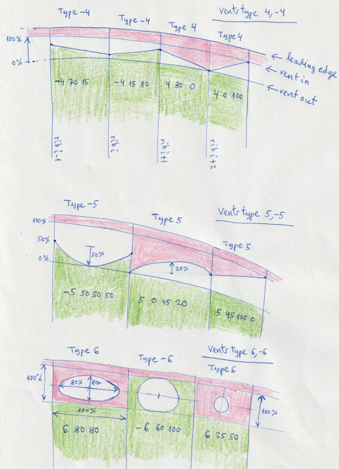
SECTION 26. GLUE VENTS
Added the following vents types, fully functional:
- Vent type 4 (general diagonal vent, adjustable at left and right, attached to extrados)
- Vent type -4 (general diagonal vent, adjustable at left and right, attached to intrados)
- Vent type 5 (general arc vent, adjustable at left, right, and arc depth, attached to extrados)
- Vent type -5 (general arc vent, adjustable at left, right, and arc depth, attached to intrados)
- Vent type 6 (ellipse inlet, with two parameters indicating widths of the ellipse on x and y axes, attached to extrados)
- Vent type -6 (ellipse inlet, with two parameters indicating widths of the ellipse on x and y axes, attached to intrados)
Note
that type 4 also includes cases 0,1,2,3, and type -4 cases 0,-1,-2,-3.
Finally type 5 includes case 4, and -5 includes case -4.
See the explanatory drawings in the manual. Read more here.
SECTION 32. PARAMETERS FOR PARTS SEPARATION
This
is a new section (!). It is MANDATORY to add this section from version
3.17 of the program. I don't like adding new sections, because it
increases the number of settings and complexity of the input file, but
it's necessary. However, SECTION 32 is an invariant section (not
required to customize for each design), and in its simplest version, it
is reduced to writing the parameter 0.
The
program separates the different pieces (panels, ribs, ...) drawn in 2D
automatically, trying to not overlap with each other or put outside the
drawing box. However, sometimes the separation between the pieces is
not as we would like. Therefore, we have added some parameters to
modify the automatic separation criteria. These are coefficients,
around 1.0 that reduce or increase the separations in horizontal (x) or
vertical (y) directions. If in doubt, you do not need to change any of
the parameters in this section, leave the default values to 1.0, or put
a single parameter 0 at the beginning, which is equivalent to
maintaining the default default values. Read the manual to know the
meaning of each value. Read more here.
Example 1:
*******************************************************
* 32. PARAMETERS FOR PARTS SEPARATION
*******************************************************
0
Example 2:
*******************************************************
* 32. PARAMETERS FOR PARTS SEPARATION
*******************************************************
1
panel_x 1.1
panel_x_min 1.0
panel_y 0.9
rib_x 1.0
rib_y 1.15
parameter6 1.0
parameter7 1.0
parameter8 1.0
parameter9 1.0
parameter10 1.0
OTHER MINOR FIXES included in version 3.17:
- Bug fixed on horizontal straps length type 1 (an error that only affects versions 3.15z and 3.16)
-
Width of horizontal straps type 1, now only affected once by the
general scale factor (at 3.15z and 3.16 it was multiplied twice)
- Start and end points of the nylon rods now marked with two blue dots.
- Font size in the lines list is now defined by mark type9, third parameter, in SECTION 20.
-
As of this release, the LEparagliding executables are "statically
compiled". This means that some Fortran libraries are automatically
added to the .out (Linux, OSX) and .exe (Windows) executable files. In
theory, this will help run the program on the computers of users who do
not have Fortran compilers installed. The regular user does not need to
know anything about this. But if you are curious and want to know what
is the instruction used for static compilation is the following:
gfortran -static-libgfortran leparagliding.f
gfortran -static-libgfortran pre-processor.f
VERSION 3.18 (2022-03-06)
1)
In section 32, I enabled a coefficient called "rib_1y" which is used to
vertically move type 1 or type 11 horizontal straps so they don't
overlap with other diagonal V-ribs. Using rib_1y = 1.0 it is printed as
always, using rib_1y = 1.8 the horizontal straps are above (experiment
with different values of the coefficient, also with negative numbers)
2)
The name of the new version is "Vinebre", a town in Catalonia.
3) Added the noNAN.sh bash scipt. Unable to open dxf file. The NaN problem.
I
mentioned this problem earlier. Sometimes, when doing mathematical
calculations, with a certain angle or numerical value, there is a
division by zero or another illegal operation. When this happens, the
Fortran executable writes the value "NaN", which means "Not a Number".
When writing the NaN value to the DXF file, some CAD programs do not
know how to interpret it correctly and cannot open the file. For
example, this happens with Autocad, but not with LibreCAD. To resolve
this issue, you can open the dxf file with a word processor (for
example, Word, or gvim) and automatically replace the NaN text string
with the numeric value 0.0
This
solves the problem. If you are using a Linux operating system, Mac OSX
with console, or Windows with cygwin console, copy the noNAN.sh script
to the lep folder and run the script as ./noNAN.sh
This will automatically change the NaN values to 0.0 and repair the dxf file.
This script can also be run directly from the console as:
sed -i 's/NaN/0.0/g' leparagliding.dxf
VERSION 3.19 (2022-05-22)
In section 29, all the "Print parameters" are now active.
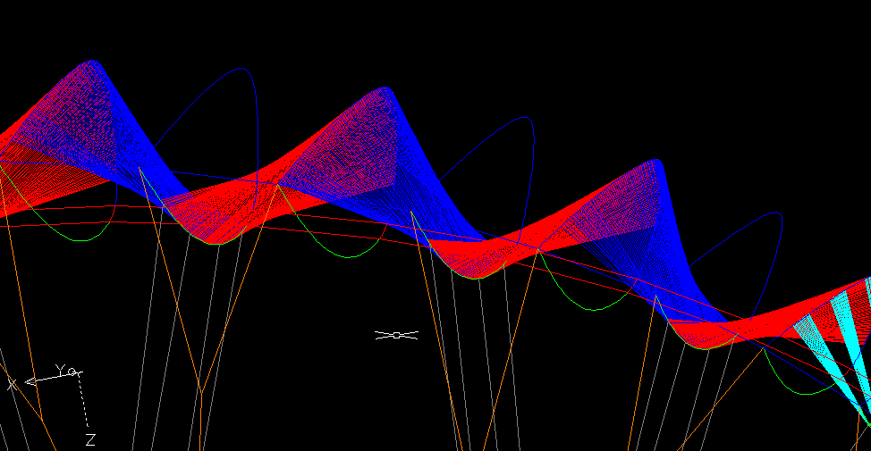
Optional 3D tessellation in lep-3d.dxf
New file lep-3d-surfaces.dxf automatically generated
New file lep-3d-surfaces.scad automatically generated (view in OpenSCAD)
New file lep-3d-surfaces.stl automatically generated
The .stl file it is generated with the intention of being able to
analyze the whole wing with a CFD program. Some colleagues are already
working on this
Example 5: Use minimal 3D shaping definition, and enabling the external DXF, SCAD, and STL files.
*******************************************************
* 29. 3D SHAPING
*******************************************************
1
1
groups 1
group 1 1 1
upper 0 1
lower 0 1
* Print parameters
Inter3D 0 1 1 0
Ovali3D 0 1 1 0
tesse3D
1 1 15
1 > Enable 3D tessellation in lep-3d.dxf from panel 1 to
15 and do symmetrical
exteDXF
1 1 15
0 > Enable 3D tessellation in independent file
lep-3d-surfaces.dxf from panel 1 to 15 and do one side
exteSTL
1 1 15
1 > Enable 3D tessellation in independent file
lep-3d-surfaces.stl from panel 1 to 15 and do symmetrical
More details here
VERSION 3.20V (2022-09-20)
Read full report here (pdf)
VERSION 3.21T (2023-01-10)
Development version, only source code: leparagliding.f
VERSION 3.23 (2023-12-11)
1) ANGLES
BETWEEN AIRFOIL PLANE AND GLIDEPATH LINE (phi) and local AoA
(chi) (Section 12 of lep-out.txt)
Improvement in internal code. Calculus of phi and chi angles reported in section 12 of lep-out.txt
Arnaud Martinez realized that there was a calculation error in the program's code. When calculating the angles phi and chi,
the
assiette of the wing was not taken into account (!)The calculation was
made as if the assiette was always zero, which is not always true. Now
fixed.
In section 37 of leparagliding.txt we have activated an new optional
code (arbitrary value 2003) which is used to indicate the angle of
assiette desired by the designer, for the wing.
If this code and angle is indicated, this is the assiette taken into
account to calculate chi and phi, bypassing the program's internal
calculation for tetha.
Example section 37 of leparagliding.txt, setting and assiette of -1º:
2003 -1.0
2) In SECTION 4, added holes "type 4". Rectangular holes, request from Pawel Lipski.
Rectangular holes with rounded corners. Parameters are very similar to triangular holes type 3.
If the hole is type 4, type in a horizontal line:
integer : 4
real : x Distance from LE to main rectangle corner in % of chord
real : y Distance from chord line to main rectangle corner in % of chord
real : a rectangle width as % of chord
real : b rectangle heigth as % of chord
real : Rotation angle (degrees) relative to chord line
real : Radius (%) of the smoothed corners
real : 0. (not used)
real : 0. (not used)
The main vertex or reference vertex of the rectangle is the bottom left.
If the width value (a) is positive, the rectangle is drawn to the right of the main vertex.
If the value of (a) is negative, then the rectangle is drawn to the left. Similar to the case of triangular holes.
VERSION 3.25 (2025-01-10)
Small changes compared to previous versions 3.23 and 3.24. Version 3.24 never oficially released, Only sent to some enthusiasts!
1) Some internal code corrections to avoid warnings and errors generated with the new Fortran compiler "Flang".
Suggestion from Lorenz Lechner - OpenGlider ( https://github.com/looooo/ ), who has worked with scripts for automatic cross-platform compilation Windows/Linux/OSX. Thanks! More information here:
https://github.com/looooo/leparagliding/actions/runs/12678783683
https://github.com/looooo/leparagliding/releases/tag/main
2) Proposed by Pawel Lipsky (Altair Paragliders).
SECTION 15 Extrados colors and SECTION 16 Intrados colors
It is now possible to define color cuts according the method "2":
Write by lines:
integer
Write the NEGATIVE integer -2, thus the program uses case 2
integer
integer is the number of panels with colored cuts
Then, for each panel with color cuts, write two lines:
integer1 integer2
Where integer1 is the panel number, and integer2 the number of cuts in this panel
integer real1 real2 real3 real4
Where integer is the cut number, starting with 1
Where real1 is the cut to the left of the panel in % from the trailing edge
Where real2 is the cut to the right of the panel in % from the trailing edge
Where real3 is the width in mm of the seam edge to join colors
Where real4 is the number 0.0, unused fallback parameter
continue the same structure through the next cut, and then continue with the next panel
Example:
Panels 2,3,4 with cuts. 1 cut in panels 2 and 3 with 1 cut, panel 4 with 3 cuts.
*****************************************************
* 15. Extrados colors
*****************************************************
-2
3
2 1
1 40.1 20.15 10. 0.
3 1
1 20.15 0.00 10. 0.
4 3
1 0.0 15.0 10. 0.
2 15.0 30.0 10. 0.
3 50.0 60.0 10. 0.
Same definition to define the intrados cuts (section 16).
Note: When the wing has an odd number of panels (center panel of nonzero width),
the cut to the left of the center panel (panel 1) is defined exactly on the wing's axis of symmetry,
for make symmetrical designs possible.
3) But... there is still a lot to do! We need to automate color cuts, especial wingtips,
special miniribs and many other things. In 2025 we need to program more in Fortran!
2. PROGRAM USE
The
use of the
program remains
"cryptic", but very powerful and
"easy". Thus is
only recommended for people accustomed to
work with text files containing
sorted data,
and CAD systems. No
graphical user interface, but its mode of operation does not need. Is necessary, a pre-processing of data in CAD
systems (or equivalent
analytical tools) and a CAD
post-process of the
DXF resulting files,
for printing or for the automated cutting table.
The program works by
reading some data files:
Then the program calculates and draws the glider in 2D and 3D in
a few
seconds. The results are obtained in the following files:
leparagliding.dxf
containing drawings to be interpreted and plotted with a CAD program (Use LibreCAD if AutoCAD20XX do not open)
lep-3d.dxf
containing 3D drawings model of the glider and lines
lep-out.txt
containing the
summary of the geometric and aerodynamic parameters calculated, and the
length of all lines.
lines.txt human-readable list of lines
lep-3d-surface.dxf (wing surface in dxf format, not ready yet)
lep-3d-surface.stl (wing surface in slt format, not ready yet)
Program works in GNU/Linux, Windows all versions, and MAC OSX.
3. MANUALS

