
FAQ's LEPARAGLIDING
FAQ's version 3.16 updated September 2021
LEparagliding is a very powerful program used to design paragliders and parachutes. The program is fully functional and has no restrictions on its use. First, it is necessary to read the latest version of the manual, in its versions in English or Russian. In this FAQ, clarified some aspects. If you need further clarification, write to info @ laboratoridenvol com
1. Running LEparagliding
1.1 How to run leparagliding?
1.2 Why is it so difficult to use leparagliding? There could be more easy?
1.3 I can run LEparagliding on MAC OSX?
1.4 DXF format and CAD programs
1.5 Sometimes the leparagliding.dxf file does not open with AUtocad. Why?
1.6 leparagliding pre air2dxf lepc and others executables not running in new Windows version. Why?
S1 SECTION 1
S1.1 Drawing "scale" parameter in SECTION 1.
S1.2 Wing scale parameter in SECTION 1.
S1.3 In SECTION 1, What effect does the second parameter?, boolean 1 or 0?
S1.4 "Rib geometric parameters" (x-rib, y-LE, y-TE, xp, z, beta, ...) You can put a simple example?
S1.5 Rib geometric parameters, how to calculate the "beta" angle?
S2 SECTION 2
S2.1 In SECTION 2, What effect does the parameter "displacement in cm" in the sixth column of the blog
S2.2 In SECTION 2, What effect does the parameter "
Relative weight of
the chord, in
relation to the
load" in the seventh column of the blog
PRE-PROCESS
See pre-processor
POST-PROCESS
po1.1 PANEL FORMATION IN DOUBLE AND SINGLE SKIN PARAGLIDERS
po1.2 VIEW THE CONSOLE CONTENTS WHEN PROGRAM CRASHES IN WINDOWS
1.1 How to run leparagliding?
11) Download the latest version in a .zip package
2) Unzip lep-3.XX.zip (or other version). You will see a folder "/lep" with the following files:
leparagliding.f
lep-3.XX.out (executable Linux)
lep-3.XX.exe (executable Windows)
cygwing1.dll and others .dll's
leparagliding.txt
gnua.txt
gnuat.txt
Note that leparagliding.txt contains the design of an example paraglider.
3) The program is ready to run because leparagliding do not need installation. Simply copy the folder and its content to your working directory.
4) Running the program:
4.1) In GNU/Linux systems:
Open a shell (xterm, kconsole...) and cd into the folder /lep
Execute the program typing ./lep-3.XX.out
After a few seconds, if all goes well, the console outputs OK and some new files are created in the same directory with the results of the program:
leparagliding.dxf
lep-3d.dxf
lep-out.txt
lines.txt
4.2) In WIndows systems:
Double Click in e.exe, and after a few seconds, some output files (.dxf and .txt) should appear in the same working folder.
5) That's it! Nothing spectacular! The plans are in 2D format in file leparagliding.txt and in 3D in file lep-3d.dxf. Is need a powerful dxf file editor program. This can be a major difficulty if you are not accustomed to working with CAD files types dxf / dwg. DXF format is used to work very precisely and make small changes and improvements on plans obtained. It is also used to prepare PDF files for printing, or create DXF / DWG for use in a computerized laser cutting table. Files lep-out.txt and lines.txt contains a summary of the technical parameters of the wing and the list of lines with their lengths. And you can open with any text editor. The difficulty of the design is to correctly understand and write the data file leparagliding.txt and associated profiles files. Please, study the manual.
Executables available for 32-bit and 64-bit machines, and include some .dll's libraries especific for each Windows version.
However, if desired you may compile yoursefl using a Fortran compiler.
2. Why is it so difficult to use LEparagliding? There could be more easy ?
Yes, it would be possible in the future to make a GUI (graphical user interface) to write file leparagliding.txt and profiles, graphically and interactively. Several programmers are currently working on this issue. Be patient, beacuse is a very complex task that needs a lot of work. Now I prefer to concentrate on the content and the proper functioning of the geometry routines. Write leparagliding.txt file is much easier than programming a GUI. Also, I find more neat and orderly easily write data in file leparagliding.txt that through a bunch of menus.
On the other hand, before writing the data, pre-processing work is essential, then run the program, then a post-processing work. The pre-processing and post-processing parts are very important for good design.
(... to continue and explain better pre and post-processing)
Specifying a little more the reasons why LEparagliding is difficult to use:
- Data entry must be done in a strict format, explained in the manual (which is sometimes not explained enough).
- The number of parameters that allows LEparagliding to free choice by
the designer is very high. Generally, they can be specified
individually for each profile or by groups of profiles.
- The amount of design options and theories available is quite large,
using different methods to choose from. And evolution tends to add
more.
It is recommended that the designer have several models example and
study the parameters written on them. Generally, the best way to create
a new model is based on a previous model. Thus, many parameters and
many sections are invariant (do not vary from one model to another),
and so just work on the general geometry , the profiles, and the
distribution of lines.
3. I can run LEparagliding in MAC OSX?
Yes, of course. Some have done successfully. Source code file leparagliding.f is written in "gnu Fortran". Just install a gnu Fortran compiler. Install gcc, f77, g95, fort77, f2c, gfortran, or similar to your computer.
5 Sometimes the leparagliding.dxf file does not open with Autocad. Why?
Sometimes, numerical errors occur in the calculation, usually divisions by zero, or similar. Then the program writes the parameter "nan" or "NaN" ("Not a Number") instead of a numerical value. The program interprets the DXF file as incorrect and does not open it. A solution is to
open the file with a text editor (recommended to use gvim) and to
automatically replace the "nan" or "NAN" characters with "0". This converts the DXF file interpretable by Autocad. If there are errors in the drawing, they are usually easily identifiable and easy to fix.
SECTION 1
S1.1 Drawing scale parameter in SECTION 1.
Drawing scale (1.0) is the
usual value. Is a drawing parameter that does not affect the design,
only the graphic representation of plans. If the “drawing
scale value” is set to 1.0, then the size of the rectangular boxes
that outline each of the plans, is exactly 1260 units (cm) horizontally and
891 units (cm) vertically. These measures are arbritaries, and have been chosen
in order to represent a wing with span less than 12.6 meters. The
vertical dimension is in the ratio (1/sqrt(2)) characteristic DIN
sheets of A4 or A3 size. If you design a wing with span greather than
12.6 m, a wing or two-seater, or with a large number of cells, then
you need to increase the scale of the box, for example 1.5 value (box
1890 cm x 1336.5 cm). If you draw a speed glider, perhaps you can use
a parameter like 0.8
S1.2 Wing scale parameter in SECTION 1.
Wing scale (1.0) is the usual
value. Is a design parameter. If you design a wing with this setting
specified in 1.0, you get a wing size “M” of surface “A” in
m2. If you want to make another wing of the same model but different
size, just you need change this setting, leaving all others
unchanged. For example, for size S, you can use the parameter 0.95
and the new surface is A x (0.95)^2. For a size L, you can use a
parameter 1.05 and the new surface is A x (1.05)^2.
This parameter “k”
is also explained here:
http://www.laboratoridenvol.com/info/scaling/scaling.html
S1.3 In SECTION 1, What effect does the second parameter?, boolean 1 or 0, in the line that says:
text,
boolean : Paraglider type "ds", "ss", or "pc", and parameter set to 0
or 1. If
"1"
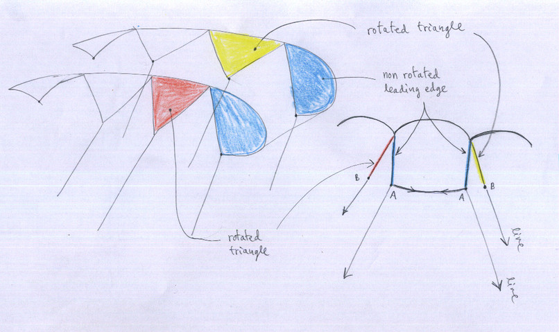
then leading edge triangles will be no rotated (only ss paragliders)
In order to correctly
calculate the lengths of the lines, in single skin gliders, the
triangles are automatically aligned in the same direction of the
forces of traction of the top lines. Indeed, according to the
distribution of the ramifications of the top lines, there are some
lines that tension in converging directions, and others in diverging
directions. But the lines anchored in the “A” row (leading
edge) do not cause rotations in profiles, because the small area of
soffit (bottom surface) prevents it. It would be possible to rotate
profiles in row “A”, but it is very rare design. This parameter leave
the freedom to do it or not by the designer. See figure “Rotated
triangles.jpg”.
A new feature in 2.35 version (not documented before), prevent
rotation of all triangles in specified ribs. This is useful for
special line designs like BHL-Pampa.
Rotated triangles
S1.4 "Rib geometric parameters" (x-rib, y-LE, y-TE, xp, z, beta, ...) You can put a simple example?
Yes, look here: Simplified.dxf
For example, paragliding 6 profiles (not a realistic model)
First, it is necessary to draw the shape of the wing (plan view in axes X-Y, front view in axes X'-Z). Take into account the orientation of the axes. It is obligatory to do so before starting to work with the program. It is better to draw using AutoCAD or similar programs. But it can also be in old style with graph paper and a pencil (also the result will be perfect, because you will be obtained numerical coordinates). Then it is necessary to measure the coordinates of the main points of the edge, the trailing edge and the frontal arc. We must also measure the angle beta.
This may seem laborious, and it is. But it is very important. The pre-processor program, helps greatly to do that.
S1.5 Rib geometric parameters, how to calculate the "beta" angle?
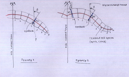
Consider the scheme of the wing, in a front view (see Figure below):
- Profiles, in blue
- The main axis of the arc of the wing, in the red
- Draw a vertical line at the point of intersection between the profile (blue), and the main axis of the arc of the wing (red)
- The angle beta, is by definition the angle between the profile lines and the vertical reference line.
Geometrical
conditions to be considered is that the profiles are taken (usually),
perpendicular to the reference axis red (the arc of the wing). That is,
90 degrees between the red and blue line. This condition is not
mandatory. That is, it was possible to make profiles with angles other
than 90. However, in the central part of the wing, it is better to make
them perpendicular 90 degrees.
S1.6 LEparagliding, pre, air2dxf, lepc, and others executables not running in new Windows version. :-( Why?
If you use windows, ADD file appropiate "cygwin1.dll" in the same folder as a.exe or lep-2.85-win.exe executable file
There are various cygwing1.dll versions...
Select the appropiate for old XP or similars o for Windows 10 and similars...
If in your system is already installed the cygwing console, then it is not necessary add the cygwin1.dll in working folder
These new "cywing1.dll" for Windows10 are included in lep-2.85-win
SECTION 2
S2.1 In SECTION 2, What effect does the parameter "displacement in cm" in the sixth column of the blog ?
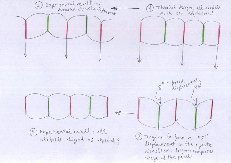
See attached figure “delta
displacements.jpg”. The wing is designed basically putting profiles
into space, and then calculating and obtaining the shape of the
panels in top and bottom surfaces.
- The theoretical situation would be that
is shown in Figure 1.
- But the experimental result is always
shown in 2. Profiles without lines are misaligned with respect to the
loaded. Due to the distribution of forces.
- One option is perhaps force the
misalignment of not loaded profiles with a shift “delta” ialong the "Z" axis as shown in Figure 3. Calculated shape of the
panels would be ideal for this form.
- The experimental result should be shown in
Figure 4, all aligned profiles.
Though this theory I have not been able to
experiment with sufficient detail. At first glance, Figure 3, seems
to cause an effect completely opposite to the expected (even more
distortion than figure 2). In short, this is an experimental
parameter, and if in doubt, leave the delta displacement at 0 cm. To
limit the movements in not loaded profiles, the solution are the
diagonal ribs.
Relative delta displacements in "Z" axis
S2.2 In SECTION 2, What effect does the parameter "
Relative weight of
the chord, in
relation to the
load" in the seventh column of the blog
To calculate the alignment
of the lines in space, LEparagliding use the theory consisting of align with the
center of gravity of the anchor points corresponding of each line (or
riser). The simplest solution to get the center of gravity of n
points in space is to get each of the coordinates x, y, x as
arithmetic mean: sum of each of the values divided by the total
number of values. This would be correct if each anchor point support
it exactly the same load. But it is not. Therefore, the program uses
a weighted average, considering a load distribution in % in A, B, C, D,
E. .. and also the length of the airfoil chord. I think I have to explain this
in more detail. It is possible to manually assign relative weights of
each rib. This parameter allows the designer manually assign relative
weights of each rib. It is an advanced parameter, which is not yet
fully implemented.
POST-PROCESS
po1.1 PANEL FORMATION IN DOUBLE AND SINGLE SKIN PARAGLIDERS
 The program draws the panels in three parts:
- Extrados (upper surface)
- Panel to close inlets
- Intrados (bottom surface)
Panels inlets (vents), are drawn without seam edges added.
In general, if the air intakes are designed open (normal), no need to consider these panel. But if some cells are considered closed (for example, near the wing tips), you need to add these panels to the design.
In double surface paragliders, these panels can be added at the Intrados panel using the CAD program.
In single skin paragliders, is practical, consider all the air intakes "closed", and add (using CAD) these panels to the top surface, thus forming part of the monolayer single skin. This is how the BHL's models were made.
This is part of the "post-process" on the plans in CAD format (DXF).
Using CAD, it is possible to cut circular holes, elliptical, or any form of cuts, on inlet panels, to create special shapes.
Since version 2.85 this
laborious process of "gluing" vents to the intrados or extrados, is
automatically performed and controlled individually for each panel in
section 26 of the data file.
po1.2 VIEW THE CONSOLE CONTENTS WHEN PROGRAM CRASHES IN WINDOWS DUE TO AN INCORRECT DATA ENTRY
There is a simple simple solution to write a Logfile.txt and see all
the contents of the console, to know where the program crashes, and the
numerical nature of the error.
1) Write te following inside a .txt file (where lep-3.10-win64.exe is exactly the name of you .exe version):
lep-3.10-win64.exe > Logfile.txt 2>&1
type Logfile.txt
PAUSE
2) Rename the file as lep-3.10-win64.bat and put inside the /lep folder
3) Double click in lep-3.10-win64.bat and the program runs and
generates a Logfile.txt file with all the contents of the console,
where you can identify the section where the data reading ends, and
some information about the nature of the error. Open Logfile.txt using
Wordpad or similiar editor which places the lines one below the other.
index

 The program draws the panels in three parts: