[en] [fr] [ru]
gnuComet
Putting fun back to the early 90's !

| Size |
M |
| Surface (m2) |
25 m2 |
| Flat span (m) |
10.33 |
| Flat AR |
4.27 |
| Cells |
28 |
| Closed cells |
4+0,5+0,5 |
| Weight range (Kg) |
60-80 |
| Glide ratio |
5.9+ |
| Anchors per rib |
4 |
| Risers |
3 or 4 |
| Extrados and intrados |
ripstop 40 gr/m2 |
| Ribs |
ripstop 40 gr/m2 hard |
| Lines (m) |
367 m |
| Normal risers |
Yes |
| Vario seat |
Yes |
| Certification |
No |


 |
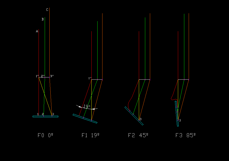
Figure 2. Consider
a three-point control harness. Risers A (red), B (green) and C
(orange), are fixed to a seat with padded rigid plate at points 1,2 and
3. Riser A is fixed at point 1 '' with a spacer up to point 2 '' where
riser B slides freely, and another spacer up to point 3 '' where riser
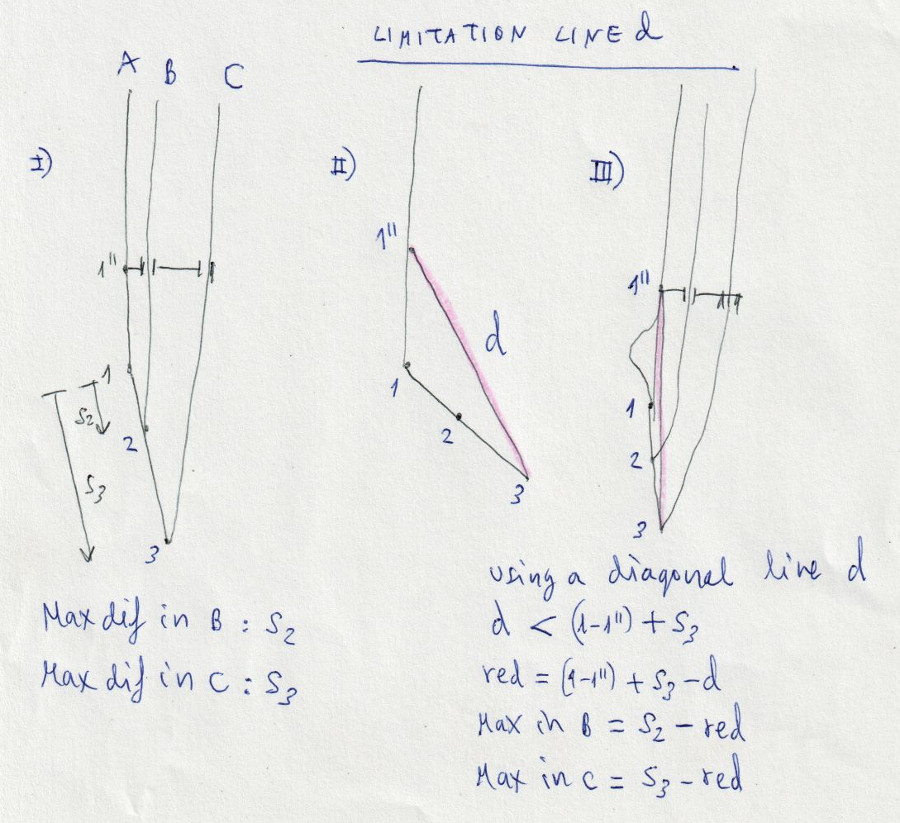
C slides freely. We can consider a first simplified model where point 1 is fixed, and the plate rotates an alpha angle with respect to this point. Tilting our weight forward, the plate rotates a positive angle. Point 2 moves to position 2 ', and riser B slides up through point 2' '. Point 3 moves to position 3 ', and riser C slides up through point 3' '. The result is wing acceleration. By tilting the weight backwards, the alpha angle is negative, and the result is the slowing of the wing. This way we can adjust the angle of incidence of the wing dynamically and intuitively. The control is complemented by moving the weight of our body to the side where we want to turn. Thus additional control with the commands is less necessary. Now let's calculate what is the elongation or shortening caused on the risers by an alpha angle on the rigid plate. If we look at the detail drawing at the bottom right, point 2 moves to a 2 'position. Considering orthogonal axes centered at point 1, and s2 the separation between points 1 and 2, the coordinates of point 2 'are: 2'x = s2 · con (alpha) 2'y = s2 · sin (alpha) The distance between points 2 'and 2' 'is calculated by its coordinates, which are known: dist(2'-2'')=sqrt((2'x-2''x)^2+(2'y-2''y)^2) And the same to calculate the distance between points 2 and 2'': dist(2-2'')=sqrt((2x-2''x)^2+(2y-2''y)^2) The experimental elongation for riser B is: dist (2-2 '') - dist (2'-2 '') And the lengthening of riser C calculated in the same way: dist(3-3'')-dist(3'-3'') Now, we have a good mathematical approximation of how the lengths of the risers vary, depending on the geometry of the steering seat. The next step will be study other possible configurations of the position of the plate and risers assembly, and study the need to add diagonal lines to limit extreme plate positions, if necessary. |
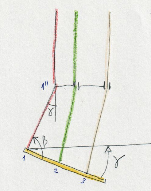 |
Figure 3. The steering seat can
take other geometric forms in flight. We consider a model where the
strap 1-1 '' turns a gamma angle at point 1 '' with respect to the
vertical, and the seat plate is still perpendicular to the strap 1-1 ''. We see that this is approximately equivalent to rotate the seat plate an angle -Alpha in the previous model. That is, if we turn a gamma angle we get a lower speed, and if at the same time we apply an angle -Alpha, we accelerate. Combining Angles Gamma and Alpha we get different configurations. Generally, Gammma angle will be small, and we consider Alpha angle as more representative of the model. |
| A | 72 | cm | A riser |
| B | 82 | cm | B riser |
| C | 90 | cm | C riser |
| 1-1’’ | 32 | cm | |
| s2 | 4 | cm | |
| s3 | 11 | cm | |
| r2 | 5 | cm | |
| r3 | 9 | cm | |
| 1’’-3 | 33,8 | cm | |
| d | 34 | cm | Diagonal strap |