1. Skin tension defintion and importance
2. Ovalization of simple panels
3. Ovalization of real panels
4. Changes of the law of ovalization in each side of teh panel
1. Skin tension definition and importance
With the concept of "skin
tension", we are referring to the methods used to convert flats panels, in curved panels (curved mainly in this
transverse direction). Other equivalent ways to name this concept are
"ovalitzation", "ballonement", or "increases in lateral width". We
previously described this concept, in the book Paraglider Design
Handbook chapter 6,
and it is necessary to review the concept there. The practical
application of the concept in the design of paragliders, has been
implemented in the section 5 Skin tension and in the section 31 New skin tension of the program LEparagliding.
When more plan is the panel, we say that has more tension in the skin.
But to get real tension in some parts (leading edge, trailing edge) it
is necessary that other parts of the panel have "little" skin tension,
because what counts are the differences in relation to tension. The
amount of tension is defined with the "law of the variations of skin
tension" (or law of variation of the increments of the widths).
The correct definition of the skin tensionand its variations along teh
border of the panel is a concept essential for the final quality and
solidity of the wing. For this reason, it is worth of thinking and
studying in detail this. And the parameters are difficult to decide,
because it is difficult to imagine the final result. Normally we use
the laws of skin tension of the skin described in section 5 of the
program, having been used with success in many paragliders (gnuLAB2,
gnuA13, BHL1, BHL2, ...). In section 31 of the program we open a much
more extensive control and new possibilities. In the following figures
I try to explain what are the concepts in order to define a
control more precise, and some of the geometric definitions used in the
programming.
The concept of "3D-shaping" is just an extension of the concept of skin
tension, but thinking in two directions, the transverse and the
longitudinal. In this also we are working on.
2. Ovalization of simple panels

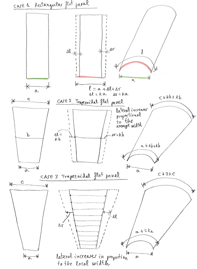
We consider the three cases of the figure above.
The CASE 1 is a flat and rectangular panel of width a. If we add a constant increment of width Dl and Dr on each side, we get an uniform ovalitzation throughout the panel. The CASE 2 is a trapezoidal panel of bases a and c and average width b. We can define the increases in lateral width, proportional to the average width og the panel b, where the value k is the law of variation of widths (Dl=k·b, Dr=k·b).
This system is used normally, given that the paraglider panels have a
width substantially constant. The CASE 3 is similar to CASE 2 except
that the width of reference of the panel is calculated at each point.
This without a doubt will allow for a more precise skin tension
(although still it is not possible to detect if the effect will be very
noticeable). Soon to be incorporated in section 31 of the program this
method 3 of calculation, as an option.
3. Ovalization of real panels using median width o local width

Soon to be incorporated in section 31 of the program this method, as an option.

And a small detail (for the
purpose only of programming). The increases in width, can be set
perpendicular to the contour (as it is calculated LEparagliding at
present), or in prolongation of the line that joins the points
corresponding to the left and right of the panel (this option is under
study).
4. Changes of the law of ovalization in each side of teh panel

A comment on where to apply
the tension of the skin. In the formulation traditional simplified
(section 5 of the program) the skin tension is applied to the panels,
all the panel of the wing, taking into account for each one of them its
mean width, and a single law of increase of width. But the extended
formulation (section 31) the skin tension is applied to each edge of
the panel in coincidence with a rib. For this reason, we can say that
we apply a tension in each "rib", to the panel on the left and the
panel to its right. As it is now possible to define a law of increments
of the widths differently for each rib, a panel may have a different
tension on their left and to their right. And what counts is the sum of
increments (or decrements if value is negative) to left and right.
See example figure.
According to the new section 31, panel width increments are defined on
each rib (not on each panel). For example, if in rib number "i" maximum
ovalization is set to 3%, this means that the edges of the panels to
the left and right increase by this amount (relative to the average
width of the panel). If in rib number "i+1" we
define a maximum ovalization of 2%, it is applied to the edges of the
two adjacent panels. In the attached figure we drew a green panel that
has an increase of 3% to the left, and 2% to the right (total 5%), and
and orange panel that has an increase of 2% to the left, and 5% to the right (maximum total 7%).


