Figure 2. The polar curve
For each calage position, our glider obtains a horizontal speed Vh and
a vertical speed Vz, which form a curve called the polar curve.
Our goal is that with free brakes, our glider flies at a point close to the maximum glide angle (4).
Despite our efforts to find the ideal calage during the design phase, it is possible that
our prototype flies "too fast" (2), or "too slow" (1).
Then we have to do some tests on the ground or in flight to find the best fit...
2. Using adjustable risers
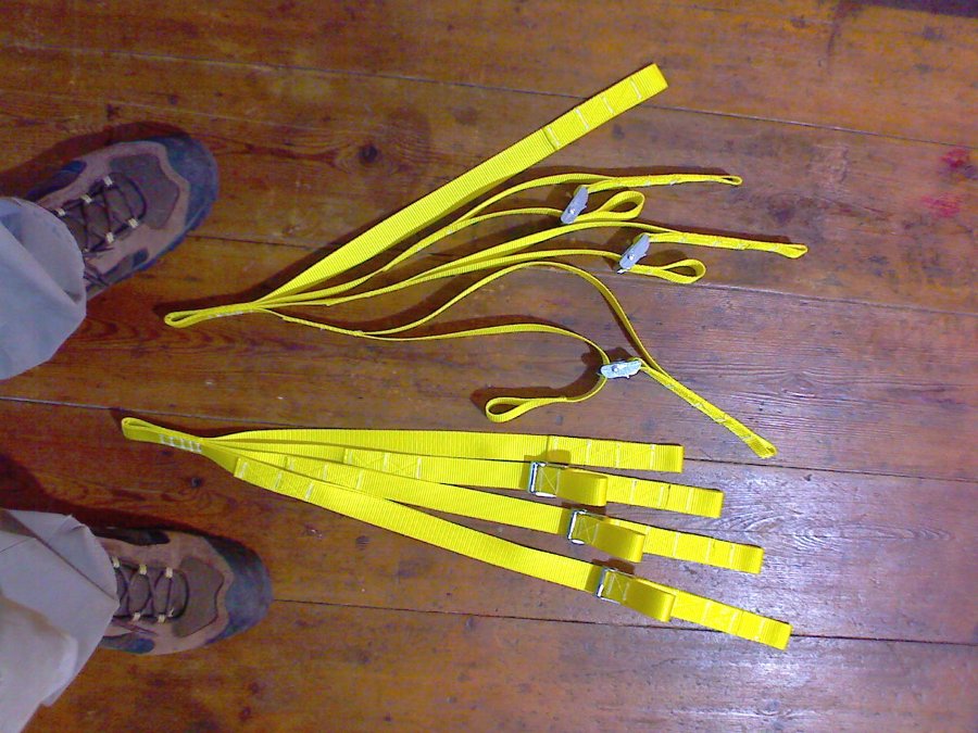
Figure 3. Example of adjustable risers used by Pere in
gnuLAB2 proto. A
riser is fixed, B riser adjustable between -5 and +5 cm,
C riser adjustable between -10 and +10 cm, D riser adjustable between -15 and +15 cm.
Schemas here and
here.

Figure 4. Example of adjustable risers used by Eric Fontaine in
his BHL5
This system is very practical and easy to use. But it does not allow to
adjust the torsion along the span. It is effective if the calage
changes are small.
A variant of these methods is to build three sets of risers, one "normal" (all risers of equal length),
one with "fast" adjustment, and one with "slow" adjustment. To test and
see which risers set provides the most similar results as expected.
3) Using line loops
An also useful technique is to make cordino loops of different lengths
+2, +3, +4, +5, +7.5, +10,... and go to our test field with laminar
wind removing and putting loops to make experiments
System works, but is very laborious... This system was used with the first prototype
BHL1, to regulate the torsion.
4) Using adjustable loops
This method was proposed by Arnaud Martínez in April 2023, and he wants to share with us.
I just wanted to share an idea that came to me today.
For the experimental calage of a new prototype, the use of special risers is useful.
On the other hand, the effect is not homogeneous between the central profile and the wing tip.
Generally the wing tip is more affected, and you end up with a setting that is not really optimal.
It is then better to also have a way to adjust the lower lines individually.
It also allows experimentation with different washout values.
I thought of a quick and easy way to do this, and I'm going to implement it on the Stork prototype.
It's about making all the lower lines 30cm shorter, and making proto extensions for the last 30cm.
I did a test of the prototype line in the picture, it works very well. It is a line with several knots and a lark's head.
You can then vary the length of the line by moving the lark's head,
without having to disassemble anything, quickly and without tools, therefore directly feasible on the school slope.
When the adjustment gives a good
result, a single line can be manufactured to the corresponding length
to replace the proto line.
Of course, the proto line needs to be a bit thicker because of the knots (Laboratori note: the reduction can be 50% or more, to be taken into consideration!)
On the other hand, it is useless to make plan A. This one can remain original. The B1 and C1 (central) too,
because the special risers take care
of it. It's just B2, B3, C2, C3. And those lines don't carry that much
weight so it's less risky too.
The idea seemed so simple and practical to me that I wanted to share it with the community.

Figure 5. Proto extensions for the last 30 cm.

Figure 6. Loop with several knots and a lark's head.


