
[en] [de] [ru]
Swoop2
parakite
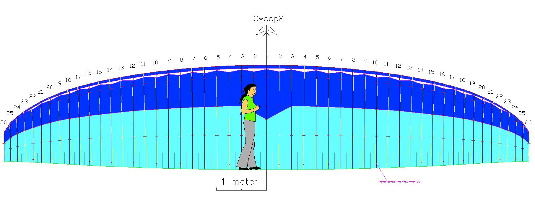
Figure 1. Swoop2 parakite colors
1. DESCRIPTION
Let's describe main changes in the new Swoop2 in relation to Swoop1. In general, since we know that Swoop1 proto #1 flies well, would not be necessary to make many changes! If we add many changes the result can be unpredictable, for better or for worse!
All the parameters of the paraglider are related to each other, and the important thing is to find the right combination. Since it is very complex to numerically model the aerodynamic behavior of the wing pressures, most designers (like me) work with good geometric models, with corrections if necessary, and using tricks that have worked well, in previous models or in other paragliders.
The overall geometry and external appearance of the Swoop 1 and 2 are almost identical. Only a very small correction of angles and lines. The main changes are in the position of the anchor points and the internal structure.
1) Putting"B" in midle point between "A" anb "C"
From a theoretical point of view, it is better to place anchor B closer to A, rather than placing B midway between A and C. This is because the vertical aerodynamic forces are not uniform along the chord, and are much greater in the first half of the profile. It is interesting to place chords where the greatest vertical forces are.
If we use a speed variation system with a rigid bar, we can anchor points A, B, C in the same proportion as they are on the wing and achieve two advantages:
- Structural optimization (better transmission of vertical forces to the profile)
- Variation of angle of incidence without deforming the profile (or with small deformations)
But for practical reasons it may be useful to place B midpoint between A and C. This is useful for using three-rise speed variation systems, where riser B has exactly half the vertical displacement of C, and A is a fixed point.
Washin is the difference between the geometric angles of attack between the center and the wingtips. It is not exactly the real washin, which depends on the orientation of the airfoil relative to the trajectory. However, in general, reducing geometric washin should improve speed (and glide ratio) and worsen wingtip stability.
Since the Swoop 1#1 has good wingtip stability, I decided to reduce a little the proto 1#2 (Thierry's) and the 22 m2 project. Swoop2 uses 5º washin.
As a precaution on Swoop1#2 and I increased the calage to 35%. Maybe at 35% the glide ratio is better, although we don't have still exact data. In a parakite this value is not critical, as it changes constantly in flight, and it is necessary to experimentally adjust the minimum and maximum range of the risers. Swoop2 would use 32.5%.
8) Lines design
The line design in Swoop 1 and 2 is the same. The only differences are the position of the anchors A, B, C and the lengths of the upper branches, which are slightly shorter.
9) New internal structure
We have replaced the individual diagonals type 16 with complete diagonals type 15. In addition to the parabolic holes, we have added some elliptical holes to the diagonals, in accordance with the new options of the LEparagliding program version 3.29 which has been developed in parallel with Swoop2.
The upper diagonal straps are type 16 (as in the previous version but now include 5 elliptical holes each.
As mentioned, miniribs also include holes.
10) Wingtip steering
This remains an option. IF necessary, a new set of lines can be created that only act on the brake points, located further towards the tip of the wing. Pull the last outher 3-4 brake points than the whole brake gallery. The glider may turn quicker.
11) Airfoil
We have kept the classic gnuReflex profile, as it has given good results. A gnuReflex-sn shark-nose version of this same profile is left for other projects.
10) Resume
2. TECHNICAL
ESPECIFICATIONS
1. DESCRIPTION
Swoop2
parakite is a 6.10 aspect ratio, 50 cells, true three-liner, reflex
parakite
(gnuReflex airfoil), successor of the Swoop1.
Developed jointly by Pere Casellas and Tim Weber. A small evolution of the Swoop1.
Developed jointly by Pere Casellas and Tim Weber. A small evolution of the Swoop1.
Differences
Let's describe main changes in the new Swoop2 in relation to Swoop1. In general, since we know that Swoop1 proto #1 flies well, would not be necessary to make many changes! If we add many changes the result can be unpredictable, for better or for worse!
All the parameters of the paraglider are related to each other, and the important thing is to find the right combination. Since it is very complex to numerically model the aerodynamic behavior of the wing pressures, most designers (like me) work with good geometric models, with corrections if necessary, and using tricks that have worked well, in previous models or in other paragliders.
The overall geometry and external appearance of the Swoop 1 and 2 are almost identical. Only a very small correction of angles and lines. The main changes are in the position of the anchor points and the internal structure.
1) Putting"B" in midle point between "A" anb "C"
From a theoretical point of view, it is better to place anchor B closer to A, rather than placing B midway between A and C. This is because the vertical aerodynamic forces are not uniform along the chord, and are much greater in the first half of the profile. It is interesting to place chords where the greatest vertical forces are.
If we use a speed variation system with a rigid bar, we can anchor points A, B, C in the same proportion as they are on the wing and achieve two advantages:
- Structural optimization (better transmission of vertical forces to the profile)
- Variation of angle of incidence without deforming the profile (or with small deformations)
But for practical reasons it may be useful to place B midpoint between A and C. This is useful for using three-rise speed variation systems, where riser B has exactly half the vertical displacement of C, and A is a fixed point.
Comparative Swoop1 - Swoop2:
|
|
A | B | C | Brake |
| Swoop 1 | 10 | 37 | 72 | 100 |
| Swoop 2 | 11 | 39 | 67 | 95 |
2) Brake section not at trailing edge
Yes, in Swoop2 we set it to 95% (similar Hegala).
3) Trailing edge miniribs
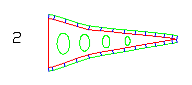
Swoop2 use new option in lep-3.29 with smooth transition, and holes inside miniribs.
Yes, in Swoop2 we set it to 95% (similar Hegala).
3) Trailing edge miniribs
Swoop2 use new option in lep-3.29 with smooth transition, and holes inside miniribs.
Figure 2. Miniribs smooth transition and holes
4) Longer nylon nose rods
We have added a longer nose rods (type 1)
We have added a longer nose rods (type 1)
|
|
Init % (extrados) | Fin % (intrados) |
| Nose jonc Swoop 1 | 10 | 14 |
| Nose jonc Swoop 2 | 18.5 | 15.5 |
5) Uppser sail rods.
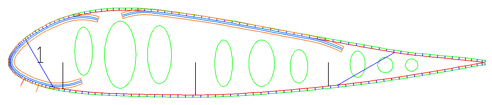
New long rods "type 4" from 23.5% to 70%. In theory this should improve the shape and stability of
the profile
6) Max geometric torsion
Figure 3. Rods type 1 (nose) and 4 (extrados)
6) Max geometric torsion
|
|
Max whasin (wingtip) |
| gnuC 1 & 2 | 6.0 |
| Swoop 1#1 | 6.0 |
| Swoop 1#2 (Thierry) & 22 m2 | 4.5 |
| Swoop 2 | 5.0 |
Washin is the difference between the geometric angles of attack between the center and the wingtips. It is not exactly the real washin, which depends on the orientation of the airfoil relative to the trajectory. However, in general, reducing geometric washin should improve speed (and glide ratio) and worsen wingtip stability.
Since the Swoop 1#1 has good wingtip stability, I decided to reduce a little the proto 1#2 (Thierry's) and the 22 m2 project. Swoop2 uses 5º washin.
7) Neutral calage
|
|
Max whasin (wingtip) |
| gnuC1 | 30% |
| gnuC2 | 33% |
| Swoop1#1 | 30% |
| Swoop1#2 (Thierry) & 22 m2 | 35% |
| Swoop2 | 32.5% |
As a precaution on Swoop1#2 and I increased the calage to 35%. Maybe at 35% the glide ratio is better, although we don't have still exact data. In a parakite this value is not critical, as it changes constantly in flight, and it is necessary to experimentally adjust the minimum and maximum range of the risers. Swoop2 would use 32.5%.
8) Lines design
The line design in Swoop 1 and 2 is the same. The only differences are the position of the anchors A, B, C and the lengths of the upper branches, which are slightly shorter.
9) New internal structure
We have replaced the individual diagonals type 16 with complete diagonals type 15. In addition to the parabolic holes, we have added some elliptical holes to the diagonals, in accordance with the new options of the LEparagliding program version 3.29 which has been developed in parallel with Swoop2.
The upper diagonal straps are type 16 (as in the previous version but now include 5 elliptical holes each.
As mentioned, miniribs also include holes.
|
|
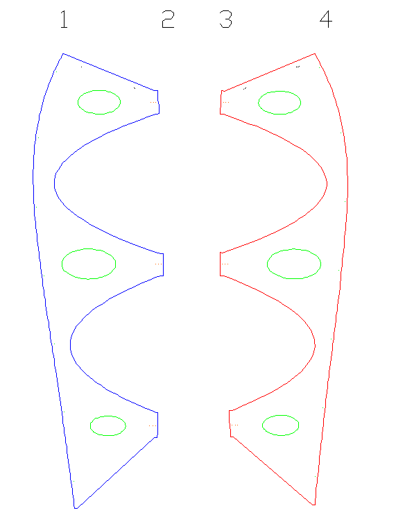 Figure 4. Full diagonals ribs type 15 |
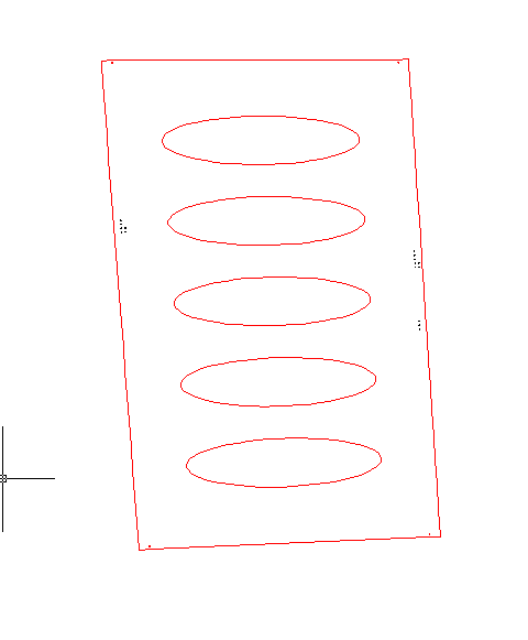 Figure 5. Upper straps type 16 with elliptical holes |
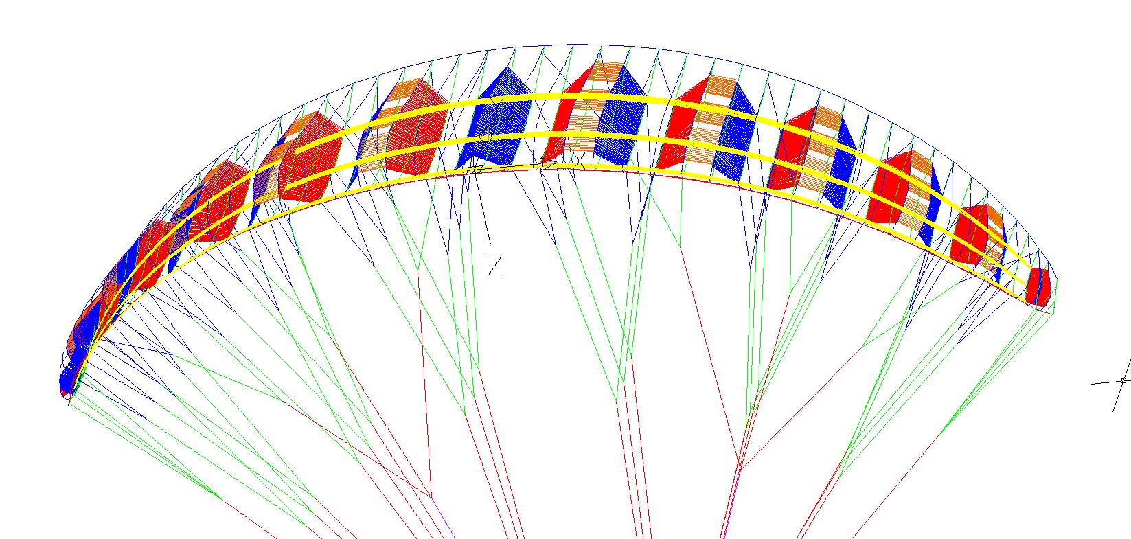
Figure 6. Swoop2 internal structure
(miniribs and internal holes not shown)
10) Wingtip steering
This remains an option. IF necessary, a new set of lines can be created that only act on the brake points, located further towards the tip of the wing. Pull the last outher 3-4 brake points than the whole brake gallery. The glider may turn quicker.
11) Airfoil
We have kept the classic gnuReflex profile, as it has given good results. A gnuReflex-sn shark-nose version of this same profile is left for other projects.
10) Resume
|
|
Aspect | Decision | Notes | Justification |
| 1 | "B" in midle point between "A" anb "C" | Yes | A=11%, B=39%, C=67% | Facilitates angle variation with conventional risers. But theoretically less adapted to load distribution |
| 2 | Brake section not at trailing edge | Yes | Brake at 95% |
|
| 3 | TE-Miniribs | Yes | Using cosinuidal transition and holes | Smoother transition |
| 4 | Create longer nylon nose rods | Yes |
|
Improves stiffnes |
| 5 | Uppser sail rods | Yes |
|
Improves stiffness |
| 6 | Max geometric torsion | 5º | Swoop1 Tim 6 deg, Swoop1 Thierry 4.5 deg |
|
| 7 | Neutral calage | 32.5% |
Swoop1 Tim 30% Swoop1 Thierry 35% |
|
| 8 | Internal structure | V-ribs type 11, 15 and 16 | Type 15 and 16 including holes |
|
| 9 | Wingtip steering | Yes | As option |
|