[en] [fr] [ru]
LEHANGGLIDING 0.11/0.2
LEhanggliding is a parametric program for hang glider designs. The main idea is
write all the numerical parameters which serve to define the
entire hangglider (structure, sail, parts) in .txt data files, and use some automation
programs to draw all the pieces and the plans.
We have selected use two programming languages for this task: Fortran and OpenSCAD. The Fortran program is used to read the data file, draw the plans, print a report, and even other files to be used as data in OpenSCAD. Using OpenSCAD we can model realistic 3D parts of the hang glider. The functionality of the current version of the program is still not complete but the system is viable and We can imagine the whole system working. Is necessary continue the work of programming and documentation.
PART 1. LEHG-F-0.11 (FORTRAN)
All the hang glider parameters can be written to a data.txt text file, and the program is responsible for drawing the wing plans in dxf format and other documents. The program draws a single-line scheme in 2D and 3D, simple but with great precision. Currently, the program version 0.11 only draws the dxf shape in plan view, but with many parameters of representation. The leading edges can be modeled in deformed shape, acording expected sail tension or forced by deflectors.
The manual for entering the data has not yet been written, but the structure of the data file is obvious. And most of the data can be interpreted by reading the file itself, and comparing the four provided examples. Important to remember that the units are cm for longitudes and degrees degrees (0-360║) for angles. Some examples below, the geometries correspond to real wings.
Download LEHG-F-0.11 including source code (lehg.f), GNU/Linux executable file (a.out), readme.txt, and all data and dxf files.
PART 2) LEHG-O-0.2 (OpenSCAD)
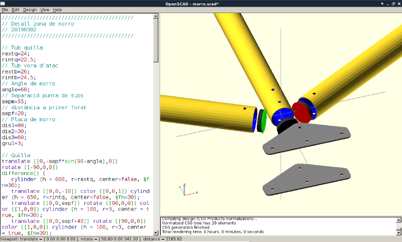
The idea is to draw each elementary piece in a module. From the smallest washer, screw, bracket, plate,... to tubing and wire. The majority of the pieces will be parametric (a few numeric values will control its shape and dimensions). A main routine will be in charge of assigning parameters and position (assembly) in space each of the elementary pieces. Some pieces of regular use may be inserted in the form of an object .stl to reduce the work of construction of the modules. Openscad allows us to export easily to .stl each of the parts built.
New drawings (october 2020):

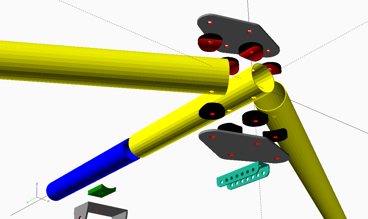

By convention, we have used a system of orthonormal axes where the y-axis follows the direction of the keel, and z the vertical direction. We consider as origin of coordinates the center of the front bolt of the nose plate. Base units is mm. As in october 2020, we currently may use the following modules:
Tube type 2 along Y axis, and multiholes (mod_tube2.scad):
tube2(tube_lenght,outher_dia,inner_dia,insertion,
hole1_dia,hole1_type,hole1_insertion,hole1_rotation,
hole2_dia,hole2_type,hole2_insertion,hole2_rotation,
hole3_dia,hole3_type,hole3_insertion,hole3_rotation,
hole4_dia,hole4_type,hole4_insertion,hole4_rotation)
hole_type=1 (= one hole)
hole_type=2 (=two holes aligned with the axis of the tube)
Keel bottom bracket type 1 (mod_kbbracket1.scad):
kbbracket1(a,b,sep)
Keel saddle type 1 (mod_keelsaddle1.scad):
keelsaddle1(a,b,e1,e2,f1_dia,f1_dis,f2_dia,f2_dis)
Saddle type 1 (mod_saddle1.scad):
saddle1(dia,h,e,dia_tub,dia_hole)
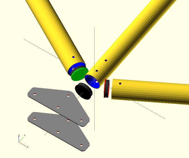
Nose plate type 1 (mod_noseplate1.scad):
noseplate1(a,b,c,r,thk)
a=distance X to LE bolt
b=distance Y to LE bolt
c=distance Y to second bolt
r=radious of the "hull" operation (the plate is the convex envelope of circles of radius r, centered at each bolt).
thk=plate thickness
Main assembly program is LEHG-0.2.scad
Notes and schemes here: page1 page2 page3 page4 page5 page6
Download all modules and main program here: LEHG-0.2.scad
We have selected use two programming languages for this task: Fortran and OpenSCAD. The Fortran program is used to read the data file, draw the plans, print a report, and even other files to be used as data in OpenSCAD. Using OpenSCAD we can model realistic 3D parts of the hang glider. The functionality of the current version of the program is still not complete but the system is viable and We can imagine the whole system working. Is necessary continue the work of programming and documentation.
PART 1. LEHG-F-0.11 (FORTRAN)
All the hang glider parameters can be written to a data.txt text file, and the program is responsible for drawing the wing plans in dxf format and other documents. The program draws a single-line scheme in 2D and 3D, simple but with great precision. Currently, the program version 0.11 only draws the dxf shape in plan view, but with many parameters of representation. The leading edges can be modeled in deformed shape, acording expected sail tension or forced by deflectors.
The manual for entering the data has not yet been written, but the structure of the data file is obvious. And most of the data can be interpreted by reading the file itself, and comparing the four provided examples. Important to remember that the units are cm for longitudes and degrees degrees (0-360║) for angles. Some examples below, the geometries correspond to real wings.
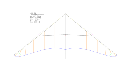 gnu-1978-style data.txt glider.dxf |
 gnuAlpha data.txt glider.dxf |
 gnuFloater data.txt glider.dxf |
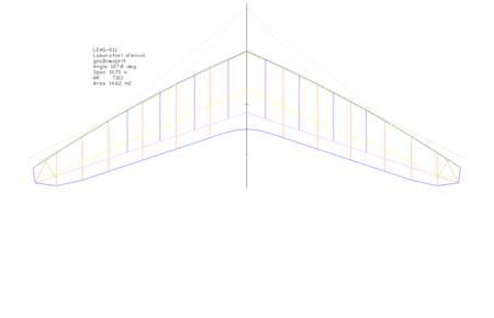 gnuBowsprit data.txt glider.dxf |
Fig 1. Four hang glider examples
Download LEHG-F-0.11 including source code (lehg.f), GNU/Linux executable file (a.out), readme.txt, and all data and dxf files.
PART 2) LEHG-O-0.2 (OpenSCAD)
The idea is to draw each elementary piece in a module. From the smallest washer, screw, bracket, plate,... to tubing and wire. The majority of the pieces will be parametric (a few numeric values will control its shape and dimensions). A main routine will be in charge of assigning parameters and position (assembly) in space each of the elementary pieces. Some pieces of regular use may be inserted in the form of an object .stl to reduce the work of construction of the modules. Openscad allows us to export easily to .stl each of the parts built.
New drawings (october 2020):

Fig 2. Nose area usig nose plates, saddles, tubes, and nose rail

Figure 3. Separate pieces through a single parameter "dz"

Figure 4. Bracket and keel saddle type 1 (fully parametric)
By convention, we have used a system of orthonormal axes where the y-axis follows the direction of the keel, and z the vertical direction. We consider as origin of coordinates the center of the front bolt of the nose plate. Base units is mm. As in october 2020, we currently may use the following modules:
Tube type 2 along Y axis, and multiholes (mod_tube2.scad):
tube2(tube_lenght,outher_dia,inner_dia,insertion,
hole1_dia,hole1_type,hole1_insertion,hole1_rotation,
hole2_dia,hole2_type,hole2_insertion,hole2_rotation,
hole3_dia,hole3_type,hole3_insertion,hole3_rotation,
hole4_dia,hole4_type,hole4_insertion,hole4_rotation)
hole_type=1 (= one hole)
hole_type=2 (=two holes aligned with the axis of the tube)
Keel bottom bracket type 1 (mod_kbbracket1.scad):
kbbracket1(a,b,sep)
Keel saddle type 1 (mod_keelsaddle1.scad):
keelsaddle1(a,b,e1,e2,f1_dia,f1_dis,f2_dia,f2_dis)
Saddle type 1 (mod_saddle1.scad):
saddle1(dia,h,e,dia_tub,dia_hole)
Nose plate type 1 (mod_noseplate1.scad):
noseplate1(a,b,c,r,thk)
a=distance X to LE bolt
b=distance Y to LE bolt
c=distance Y to second bolt
r=radious of the "hull" operation (the plate is the convex envelope of circles of radius r, centered at each bolt).
thk=plate thickness
Main assembly program is LEHG-0.2.scad
Notes and schemes here: page1 page2 page3 page4 page5 page6
Download all modules and main program here: LEHG-0.2.scad
Figure 5. openSCAD code generator, first versions
 |
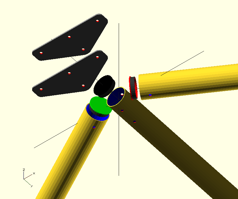 |
Figure 6. Nose plates and capends.
