The mechanical design of the structure of the delta wing can be divided in the following parts:
01- Main frame 02- Triangle and king post 03- Bowsprit 04- Deflectors 05- Cables assembly 06- Réflex lines 07- Elliptic tips 08- Truncated tips 09- Washout and sprogs 10- Noseplate assembly 11- Rear keel 12- Kingpost assembly (top and bottom) 13- Downtubes - keel assembly 14- Downtubes - control bar assembly 15- Crossbar center assembly 16- Crossbar - leading edge assembly 17- Hang point assembly 18- Variable geometry and compensators 19- Others
Each part
includes a varied group of individual pieces that can be assembled with
different design options. It is necessary to know the different options
of mechanical and select the suitable in our design. The LEHG program will take into account all these groups and select the appropriate settings for each sub-type chosen.
To start, we will study the options for the groups 13 (Downtubes - keel assembly) and 16 (Crossbar - leading edge assembly).
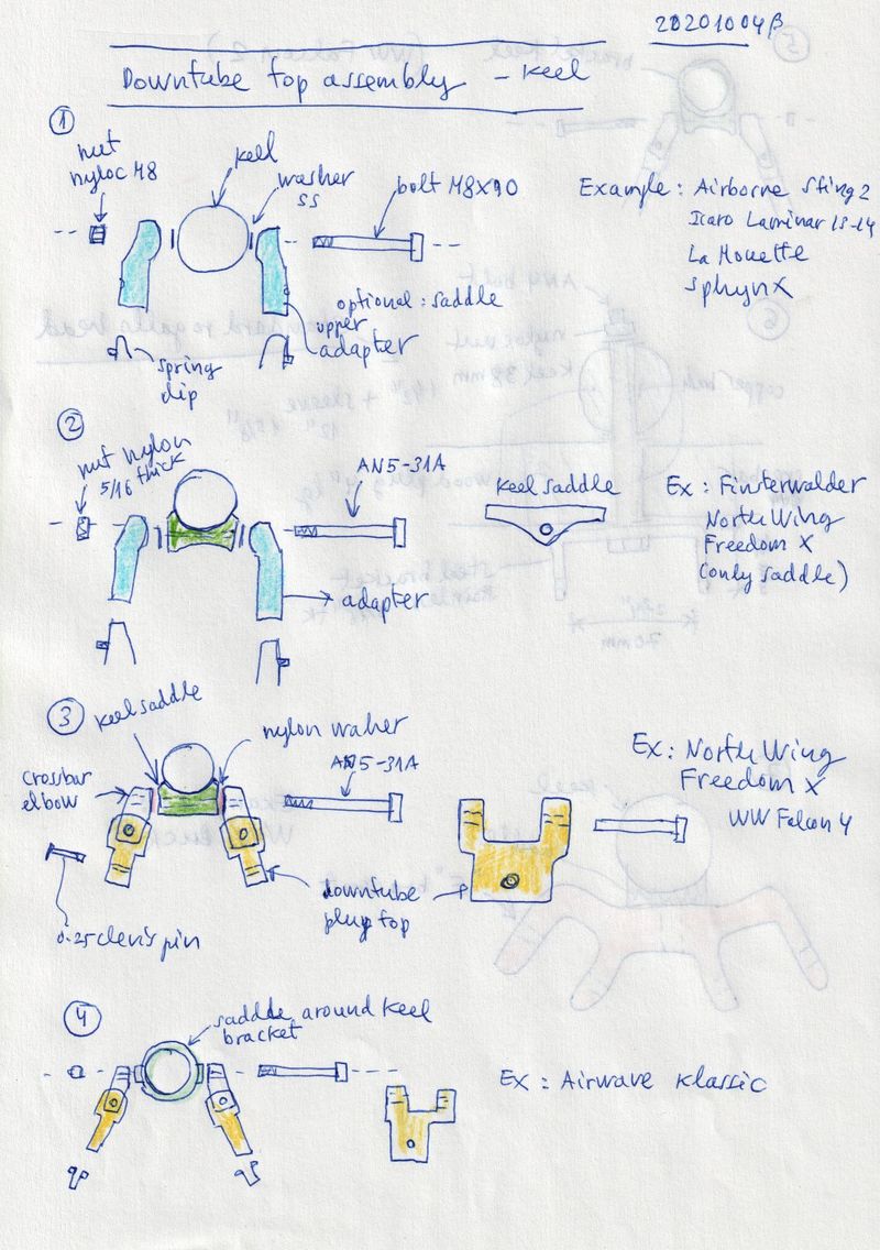
13. Downtubes - keel assembly
In this section, let's sketch the 7 sub-type, usually found (see mentioned examples).
Figure 1. A simple and effective method is to use a special piece of
adaptation at the top of the downtube, which allows rotations around
the Y-axis (keel) and the X-axis (horizontal and perpendicular to the
keel). The bolt (normally an AN5 or M8) can traverse directly the keel
by the middle of the tube. Examples: Airborne Sting 2, Icaro2000
Laminar 13-14, La Mouette Sphinx.
Figure 2: A small variation is to add a saddle or keel bracket made
from forged aluminum, and cross the main bolt AN5 here. Examples:
Finsterwalder Perfex, Noth Wing Freedom X.
Figure 3.
Some manufacturers prefer to replace the rigid piece, free in rotation,
by two pieces (crossbar elbow and downtube plug) which allow rotations
in X and Y in the corresponding bolts. Examples: Nort Wing Freedom X,
Wills Wing Falcon 4.
Figure 4. Variant with the crossbar elbow and downtube plug and bracket centered in the middle of the keel tube. Example: Airwave Klassic.
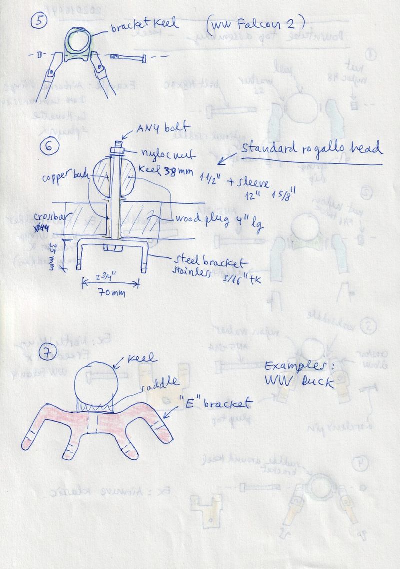
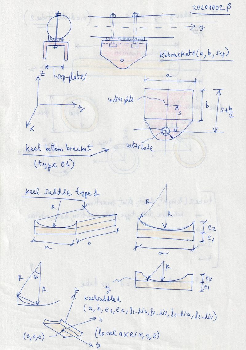
Figure 5. Same as previous but complete bracket around keel and the main bolt below. Example Wills Wing Falcon 2.
Figure 6. Classic assembly of the standar Rogallo crossbar-keel union
using an AN5 bolt (not AN4) and and stainless steel or aluminum
inverted "U" bracket. The two tubes below, bent in a vertical, fixed to
the bracket with a single AN5 bolt in the X-axis.
Figure 7.
Special "E" bracket similar to that of figure. Allows for downtubes
rigged position in the right angle, and also folded parallel to the
keel. Example Wills Wing Duck.
There are other subtypes not described here. For example, the double
articulation with brackets. Example Bautek Zephîr and Astîr. Each
subtype can be described by n parameters (geometry, classes, and
materials). In accordance to plans and technical notes that
describes the group.
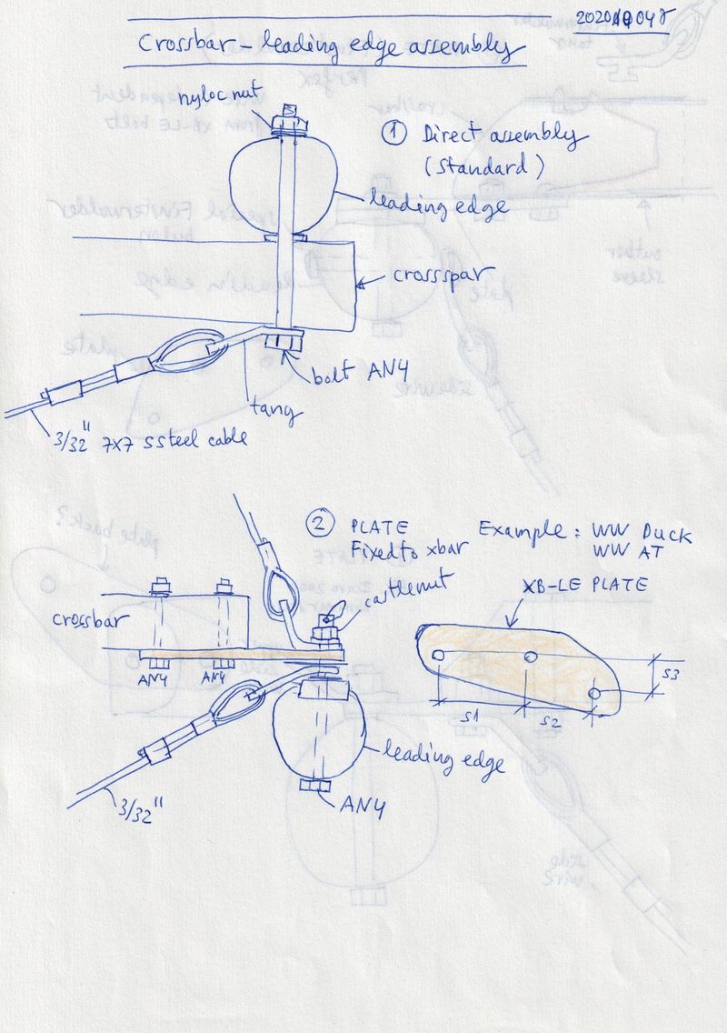
16 Crossbar - leading edge assembly
Figure 1.
Classic standard Rogallo and 70's hang gliders. One vertical bolt
joining crossbar ans leading edge tubes. Tang cables attached at the
beginning and at the end of the bolt. Normally crossbar located below
the leading edge, but it can also be the opposite. Example: Wasp Falcon
V, La Mouette Atlas.
Figure 2.
The majority of modern wings use some kind of plate or adapter between
the crossbar and the leading edge tube. A plate with three holes not
aligned is used frequently in this assembly. Plate fixed rigidly to the
crossbar with two AN4 bolts and a AN4 or AN5 bolt in the tube of the
leading edge as the point of articulation. Cable tangs top and bottom,
can be fixed at the point of articulation in each side of the plate.
This arrangement hides visually and aerodynamically the whole assembly
inside the double sail. The function of the plates, is to move away the
end of the crossbar, so that it does not interfere with the profile.
Examples: Wills Wing Duck, AT.
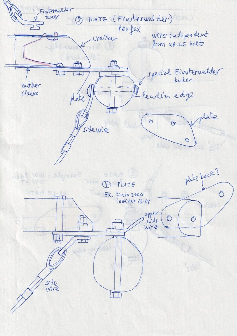
Figure 3. The ingenious Finsterwalder system will also use a three-hole
plate similar to the previous one, but it's cables are attached
directly to the tubes with the Finsterwalder tangs and quick bolts.
Notice also that the fixing of the crossbar is only on one of the lower
side of the crossbar tube, but the end of the crossbar is of double
wall, reinforced with an exterior sleeve. Example: Finsterwalder
Perfex, Airfex,...
Figure 4.
Similar to figure 2 assembly but lower side wire attached to bolt in
crossbar. Plate attachement using complete tiube in first bolt and only
one side in second bolt. The crossbar tube is beveled at the end.
Example: Icaro2000 Laminar 13-14 (kingpost).
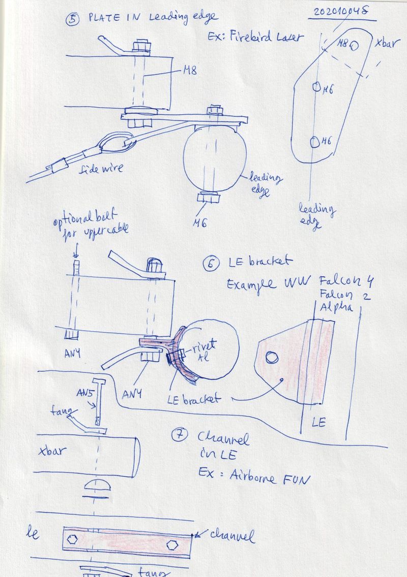
Figure 5. It also uses a three-hole plate. But fixed rigidly to the
leading edge and articulated to the crossbar. Lower tang fixet to
leading edge and upper tang to crossbar. Example: Firebird Laser (a
very strong glider). Figure 6.
Instead a three-plate hole, some manufactures uses a bracket riveted in
the leading egge, and crossbar articuled in a bolt in the crossbar.
Upper and lower cable tangs in the crossbar. Examples: Wills Wing
Falcon 2,4 and Alpha.
Figure 7. Instead of a bracket, a bolted channel can be used on the
side of the leading edge. With a disposition similar to the previous
one. Example: Airborne Fun.