
PARAGLIDER DESIGN HANDBOOK
CHAPTER 9. RISERS
9.1
Introduction
9.2. Analysis on 4
riser speed system
9.3 Trimers
9.4 Vario seat
9.1. Introduction
The
risers are
linking
the main carabiners
with
the lines and
grouped into classic
areas named
"A ", "B", "C"
and
"D",
on
each
side
of
the wing and
symmetrically.
The
simplest paragliders of
beginnings
only
had
2
risers
per
side, then
were
added, 3,
4,...
and even more,
for a better
control
of the pilot on
the
wing. With
the progressive reduction
in the number of
lines
in
the directions along
and
across the
wing, gliders
go
back with three or
two risers per
side.
Normally, the
lengths
of
the risers are
all equal to
each other, except in
the
prototypes, which
may
be necessary to make
special
risers each
of
a
different
length, to
adjust the
wing.
To
adjust the
flight
speed, risers can
be
shortened or
lengthened
using
different
devices:
-
speed bar (operated
dynamically
with
your feet)
-
trimers (manual
setting)
-
vario seat
(weight shift
back
and forth on
special
harness "sellette de
pilotage")
- rods or plates...
9.2. Analysis on 4
riser speed system
9.2.1 Statement
of the problem and analytical solution
Below
is a classic
speed
system of
4
risers,
and
the
analitical calculations of the effective
lengths of each
riser
LA, LB, LB, LC in
applying displacement
in the cord (a).

Figure 9.1 Risers length variation by applying a real speed system
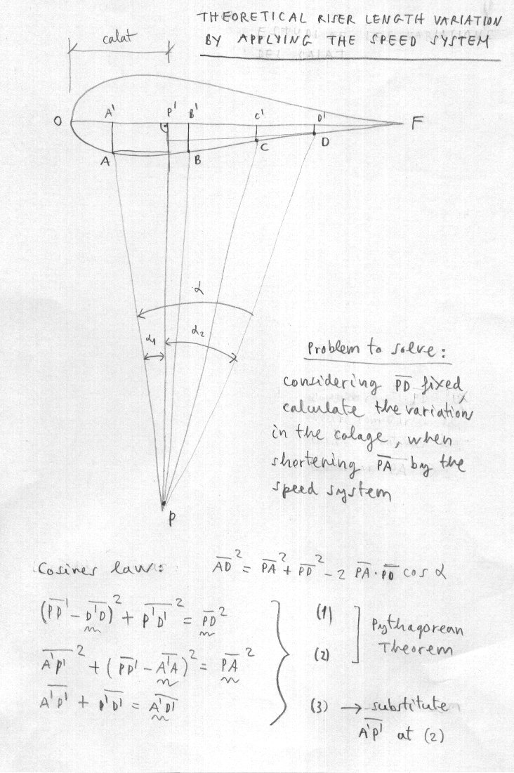
Figure 9.2. System of
equations
for
solving the problem of
calculating the
variations
in calage and
ideals
lengths
of each riser,
by
applying the
displacement (a) in the cord of the speed
system.
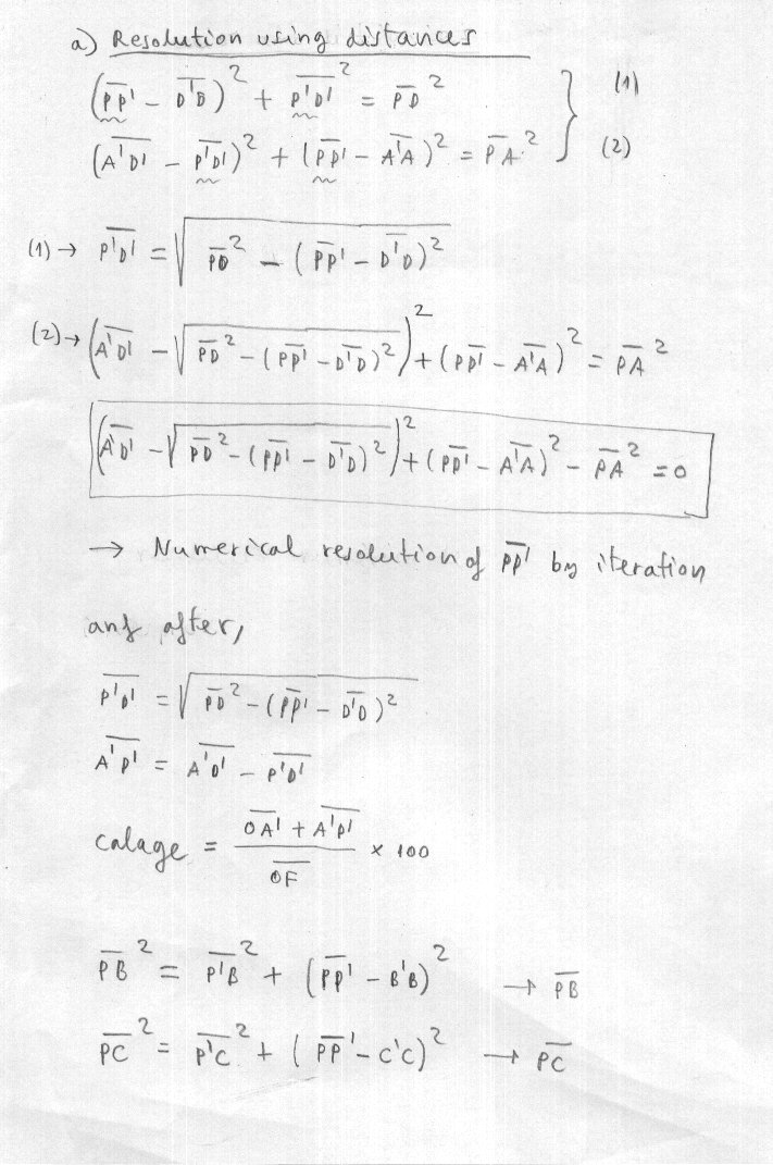
Figure 9.3. Resolution using only distances.
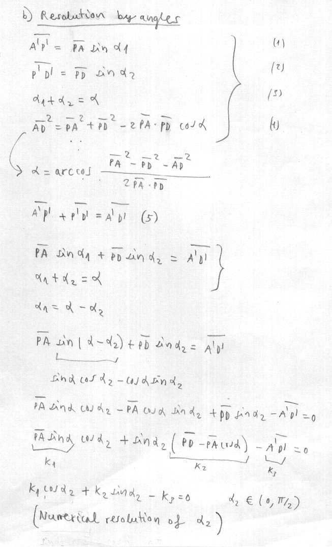
Figure 9.4. Resolution using cosine law and angles.
Distances
PA,
PB, PC, PD are considered
the
necessary to
rotate
the
airfoil around
point
D
without
deformation.
Note that in the real speed system (described
above),
distances
LA,
LB ,LC , LD approximate those
ideals
and
the
profile
is
deformed
slightly
above the
ideal
9.2.2 Numerical examples
Geometric parameters:
| OA' |
24,34 |
| A'B' |
54,41 |
| B'C' |
73,03 |
| C'D' |
68,73 |
| D'F |
65,87 |
| OF |
286,38 |
| A'A |
15,91 |
| B'B |
20,03 |
| C'C |
14,2 |
| D'D |
6,07 |
| AD |
195,81 |
| A'D' |
196,17 |
| PD |
706,2 |
|
Riser lengths real speed system |
Riser lengths ideal speed system |
|
| a |
LAR |
LBR |
LCR |
LDR |
LAT |
LBT |
LCT |
LDT |
Calage % |
| 0,0 |
47,0 |
47,0 |
47,0 |
47,0 |
47,0 |
47,0 |
47,0 |
47,0 |
40,0 |
| 2,5 |
46,2 |
47,0 |
47,0 |
47,0 |
46,2 |
46,4 |
46,7 |
47,0 |
39,0 |
| 5,0 |
45,3 |
47,0 |
47,0 |
47,0 |
45,3 |
45,8 |
46,4 |
47,0 |
37,9 |
| 7,5 |
44,5 |
47,0 |
47,0 |
47,0 |
44,5 |
45,2 |
46,1 |
47,0 |
36,9 |
| 10,0 |
43,7 |
46,2 |
46,6 |
47,0 |
43,7 |
44,6 |
45,8 |
47,0 |
35,9 |
| 12,5 |
42,8 |
45,3 |
46,2 |
47,0 |
42,8 |
44,0 |
45,6 |
47,0 |
34,8 |
| 15,0 |
42,0 |
44,5 |
45,8 |
47,0 |
42,0 |
43,4 |
45,3 |
47,0 |
33,8 |
| 17,5 |
41,2 |
43,7 |
45,3 |
47,0 |
41,2 |
42,8 |
45,0 |
47,0 |
32,8 |
| 20,0 |
40,3 |
42,8 |
44,9 |
47,0 |
40,3 |
42,2 |
44,7 |
47,0 |
31,7 |
| 22,5 |
39,5 |
42,0 |
44,5 |
47,0 |
39,5 |
41,6 |
44,4 |
47,0 |
30,7 |
| 25,0 |
38,7 |
41,2 |
44,1 |
47,0 |
38,7 |
41,0 |
44,1 |
47,0 |
29,7 |
| 27,5 |
37,8 |
40,3 |
43,7 |
47,0 |
37,8 |
40,4 |
43,8 |
47,0 |
28,6 |
| 30,0 |
37,0 |
39,5 |
43,3 |
47,0 |
37,0 |
39,8 |
43,5 |
47,0 |
27,6 |
| 32,5 |
36,2 |
38,7 |
42,8 |
47,0 |
36,2 |
39,2 |
43,3 |
47,0 |
26,6 |
| 35,0 |
35,3 |
37,8 |
42,4 |
47,0 |
35,3 |
38,6 |
43,0 |
47,0 |
25,6 |
| 37,5 |
34,5 |
37,0 |
42,0 |
47,0 |
34,5 |
38,0 |
42,7 |
47,0 |
24,6 |
| 40,0 |
33,7 |
36,2 |
41,6 |
47,0 |
33,7 |
37,4 |
42,4 |
47,0 |
23,5 |
| 42,5 |
32,8 |
35,3 |
41,2 |
47,0 |
32,8 |
36,8 |
42,1 |
47,0 |
22,5 |
LAR LBR LCR LDR (Real riser
lengths) LAT LBT LCT
LDT Theoretical or ideal riser lenghts
a= applied cord (cm)
Real riser length using figure 9.1 formulation. L=47 cm, x1=2,5
cm, b=15 cm (amax=45 cm, using 2 pulleys ).
Theretical (ideal) riser length using figure 9.2 and figure 9.3
formulations.
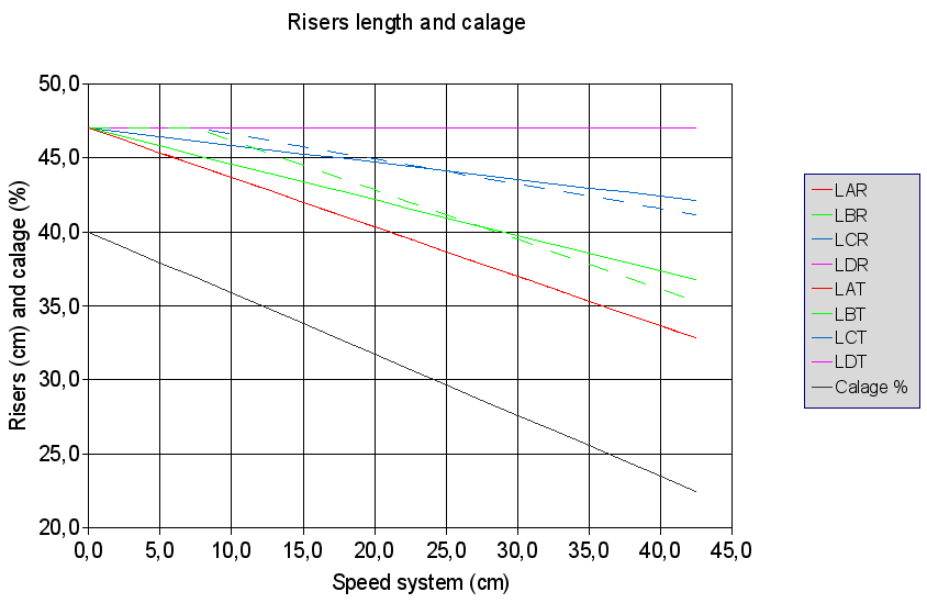
Figure 9.5. Risers lenth and calage variations with speed system.
RED ----> "A" riser
GREEN ----> "B" riser
BLUE ----> "C" riser
MAGENTA ----> "D" riser (47 cm)
GREY ----> calage %
The
solid
line shows the
ideal
lengths
to
avoid deforming
the
airfoil. The
dotted
line shows the
real
risers lengths with
an
speed
system as
shown in
Figure
9.1
and an spacer between
the
elevators
A
and
B
of
2.5
cm
index