
METHODS FOR HANG GLIDER SAIL PATTERNS
There are several suitable methods to design the sail patterns of the hang glider. Let's expose some of them.
These methods will be programmed in LEhanggliding
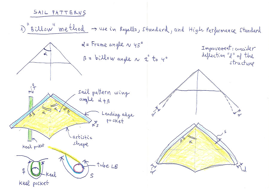
1) "Billow" method
It is a very simple method applicable to the old Rogallo, Standard and High Performance Standard wings of the 70's. It is based on considering the sail as a conical surface. Given
the angle between the keel and the leading edge, to define the sail it
is only necessary to draw a circular sector with an angle equal to the
sum of the angle between the bars of the structure (typically from 41º
to 50º) , plus the billow angle that will define the conical surface. A typical billow angle is that of 3.5º, so the angle of the circular sector will be between 43.5 and 53.5. In addition it is necessary to add the corresponding pocket surfaces for the leading edge and the keel tubes. A recommendable
improvement is to estimate the deflection of the structure, either by
flexion of the tubes in flight or by the action of deflectors (very
common at the end of the 70's). Then subtract or add proportionally, the amount of fabric necessary to compensate the deflection and obtain a smooth surface.
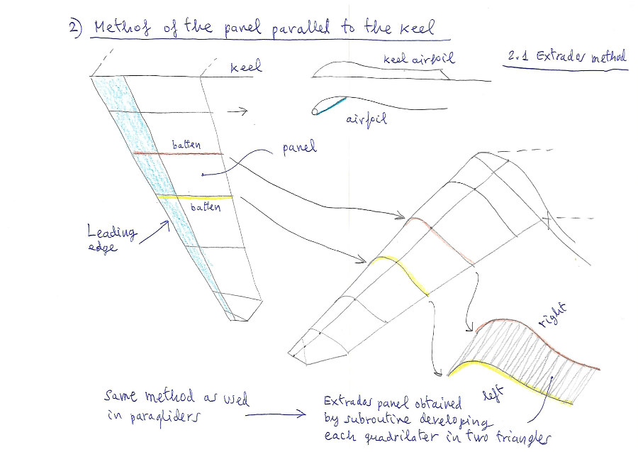
2) Method of the panel parallet to the keel
In this method the candle is defined by means of elongated panels with a side parallel to the keel. A panel delimited between two battens or an intermediate profile is considered. Thus the panel is defined by a profile on the right and a profile on the left. We must decompose each of these profiles in N points. Then
consider the successive quadrilaterals in space, consisting of two
consecutive points, and decompose this quadrilateral into two triangles
that can be developed on a flat surface. This method is exactly the same as the one used in paragliders to develop a panel between two profiles. This is used to obtain the upper surface.
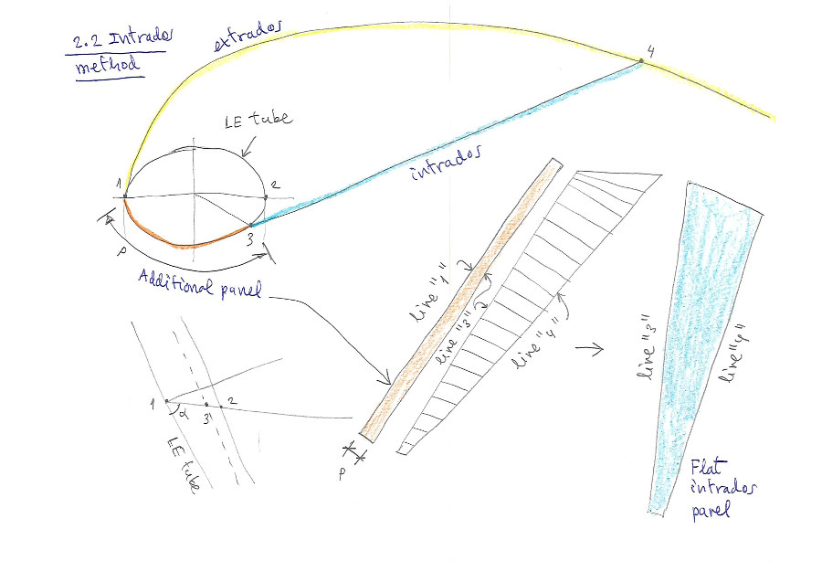
For
the intrados (lower surface) or leading edge pocket (typically in 30%
double-surfaced wings), it is possible to consider two lines in space. The
first line is formed by one of the guidelines of the leading edge tube
"line 3 in the figure", and a second line "4" that will be the seam
line between the lower and upper surface. Then we need
to divide the lines in space "3" and "4" in N points, and apply again the
subroutine of quadrilateral and triangles to develop a flat surface. Of course, line
"3" must take into account the deflection of the structure in flight,
and line "4" the shape and angle of attack of the profiles. That is why it is necessary to create a 3D reallistic model of the structure and the sail.
3) Empirical control of the distortion
Using the method of the parallel panels, we obtain very precise surfaces. But requires a lot of power of calculation (although geometrically trivial). It is unlikely that in the 1980s this method would be used. It's simpler to design a flat surface and trust that it will fit in the final 3D model! Without a doubt, this method may have been used by many constructors. Look at the sail of the Albatross:
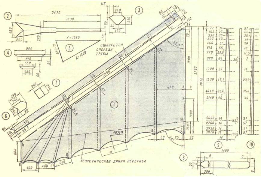
This plan suggests a very simple construction. In fact the method is the billow angle (frame 110º, sail 111º), taking into account the
distortions of the leading edge (40 mm with deflectors and 110 mm without), and the reduction of the chord of the
profile due to the curvature. A little experimentation on models may provide good results. Alternatively, the numerical experimentation on method 2 can provide data to correct the distortions with a flat sail.
4) Transversal panels method
Modern sails use panels sewn with pieces in the transverse sense (along span). I have not yet defined a method to do this. I propose the method of "suppose the problem is solved and analyze" :) Soon more information.
index