ALUMINUM ALLOYS AND HG TUBING
1. Aluminum and aluminum alloys
2. Typical aluminum tubes for HG
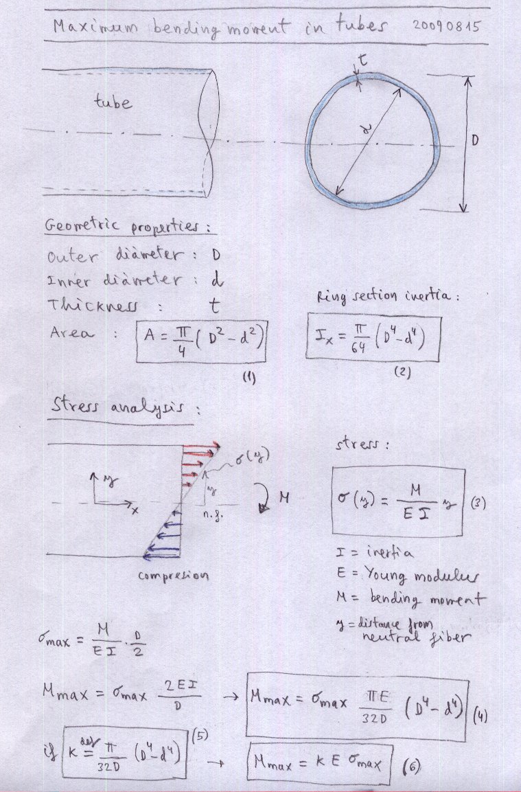
3. Maximun bending moment
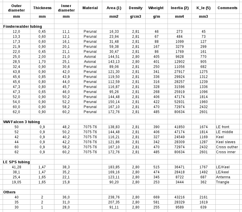
4. Aluminum tubing sizes
1. Aluminum and aluminum alloys
Tubes of typical hang gliders are made of aluminum alloys 6061-T6 and 7075-T6 (zicral) alloy types.
Aluminum alloys http://en.wikipedia.org/wiki/Aluminium_alloy
Aluminum 7075-T6 http://en.wikipedia.org/wiki/7075_aluminium_alloy
Aluminum 6061-T6 http://en.wikipedia.org/wiki/6061_aluminium_alloy
Aluminum 7075-T6 is also known for trade marks Perunal, Zicral, Ergal, Fortal Constructal.
Mechanical properties of tubes used in HG:
Table 1: Mechanical properties of HG aluminum alloy tubing.
(1) Data from Finsterwalder tubing
(2) The maximum stress a material can withstand when subjected to tension, compression or shearing. It is the maximum stress on the stress-strain curve. Note: 1kp/mm2 is aprox 10 MPa.
(3) Below the yield strength all deformation is recoverable, and the material will return to its initial shape when the load is removed. This recoverable deformation is known as elastic deformation. For stresses above the yield point the deformation is not recoverable, and the material will not return to its initial shape.
Note also that the mechanical properties of 7075 depends geratly on the temper of the materials (ultimate strenght varies from 276 to 530 Mpa in temper "0" and temper "T6".
Another important detail is that the aluminum alloy 7075 has higher density (2.81 g/cm3) that the pure aluminum (2.70 g/cm3) and other alloys, due to the alloy with zinc, manganese and copper). However, their ultimate strenght, allows small tube thickness and therefore lighter than tubes of other alloys.
2. Typical aluminum tubes for HG
2. Typical aluminum tubes for HG
3. Maximun bending moment
4. Aluminum tubing sizes
1. Aluminum and aluminum alloys
Tubes of typical hang gliders are made of aluminum alloys 6061-T6 and 7075-T6 (zicral) alloy types.
Aluminum alloys http://en.wikipedia.org/wiki/Aluminium_alloy
Aluminum 7075-T6 http://en.wikipedia.org/wiki/7075_aluminium_alloy
Aluminum 6061-T6 http://en.wikipedia.org/wiki/6061_aluminium_alloy
Aluminum 7075-T6 is also known for trade marks Perunal, Zicral, Ergal, Fortal Constructal.
Mechanical properties of tubes used in HG:
| Name-source |
Code |
Ultimate strenght (2) |
Yield strenght (3) |
Elongation |
Density |
Modulus of elasticity |
|
| kp/mm2 |
Mpa |
Mpa |
g/cm3 |
MPa |
|||
| Perunal (1) |
7075-T6 |
53-64 |
2,81 |
||||
| Avional 100 (1) |
2017A |
38-55 |
|||||
| Anticorodal (1) |
6081-T6 |
32-36 |
|||||
| Extradural (1) |
6061-T6 |
25-28 k |
|||||
| Wiki |
7075-0 |
276 |
145 |
9-10% |
|||
| Wiki | 7075-T6 |
510-538 |
434-476 |
5-8% |
|||
| Wiki | 7075-T651 |
462-538 |
372-462 |
3-9% |
|||
| Wiki |
6061-0 |
125 |
55 |
25-30% |
2,70 |
||
| Wiki | 6061-T6 |
290 |
241 |
10% |
2,70 |
||
| Mathweb |
7075-T6 |
524 |
462 |
11% |
2,81 |
71,7 |
|
| Mathweb |
6061-T6 |
310 |
276 |
12% |
2,70 |
68,9 |
|
| Aluminum (pure) |
Al |
7-11 |
2,70 |
70 |
|||
(1) Data from Finsterwalder tubing
(2) The maximum stress a material can withstand when subjected to tension, compression or shearing. It is the maximum stress on the stress-strain curve. Note: 1kp/mm2 is aprox 10 MPa.
(3) Below the yield strength all deformation is recoverable, and the material will return to its initial shape when the load is removed. This recoverable deformation is known as elastic deformation. For stresses above the yield point the deformation is not recoverable, and the material will not return to its initial shape.
Note also that the mechanical properties of 7075 depends geratly on the temper of the materials (ultimate strenght varies from 276 to 530 Mpa in temper "0" and temper "T6".
Another important detail is that the aluminum alloy 7075 has higher density (2.81 g/cm3) that the pure aluminum (2.70 g/cm3) and other alloys, due to the alloy with zinc, manganese and copper). However, their ultimate strenght, allows small tube thickness and therefore lighter than tubes of other alloys.
2. Typical aluminum tubes for HG