1.
Introduction
2. Geometric and mechanical specifications of the manufacturer Peguet 3.
Numerical model 4. Graphic results 5.
Numerical results
1. Introduction
The
stainless steel maillons (quick links) have been (and remains) an
essential
element for the union of the risers with paraglider lines. We have been
using
diameters of 5,4,3.5,3 mm and various shapes (oval, triangular, square
or rectangular, trapezoidal, especially ...) always for the best
adaptation and load transfer between risers and lines.
The maillon has always been a very good structurally, so it was never
reason to worry about their safety, except for the need to check before
each flight that are perfectly closed.
With the progressive
reduction in the number and diameters lines and use of very thin
dyneema risers
or by weight reduction in mountain paragliders, the dimensions of
maillons
goes down, so it is of interest to know the behavior theoretical and
practical (trials). This page details the internal theoretical efforts
(axial, shear, moment) taking place in the maillon.
There remains for another study analyzing tensions in the steel section
and experimentation with laboratory tests.
2. Geometric and mechanical
specifications of the manufacturer (Peguet)
Comments: CU refers to the
use load ("charge d'usage"). With loads CU or
lower, deformations produced are such that allows closing and opening
of maillon manually ... CR refers to
the breaking load ("charge de rupture") according to the manufacturer's
specifications (not published in detail). For me, without
making some numeric calculations
and real
tests, the breaking load becomes a
mystery...
3.
Numerical model
In order
to know the mechanical efforts produced in the maillon,
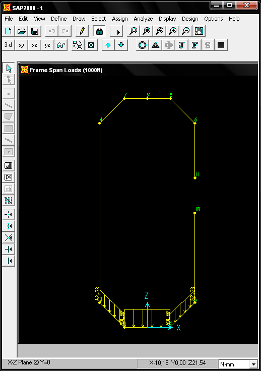
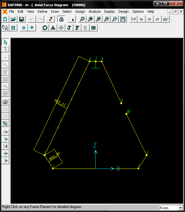
Laboratori d'Envol has modelled numerically 4 maillon 3.5 mm in
diameter:
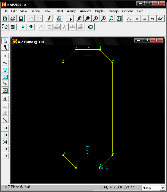
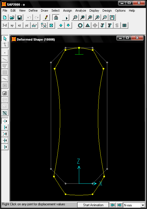
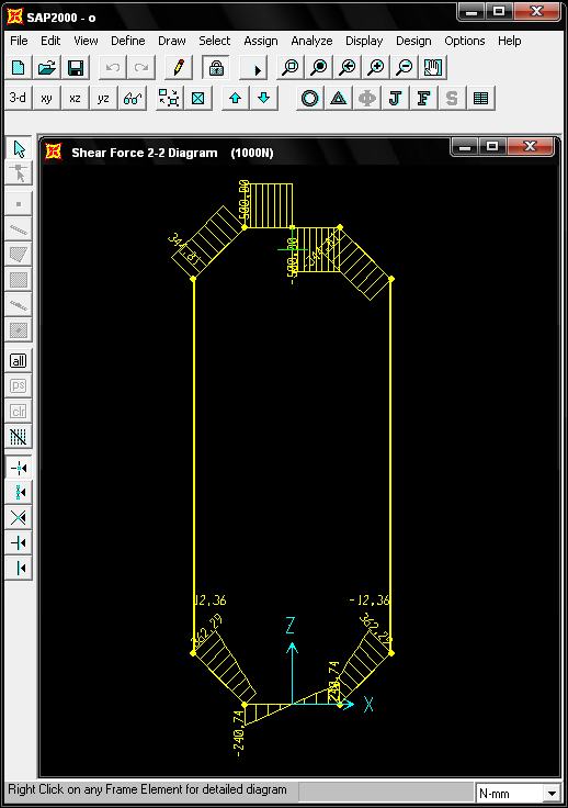
a. Maillon oval closed
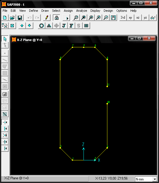
b. Maillon oval open
c. Maillon triangular closed
d. Maillon triangular open
The maillon have
modeled according to a simplified model of bars
and analysed with the program SAP2000 by the finite element method. It has
been considered a workload of 1000 Newtons (approximately 100
kg). Assuming a linear behavior, results can be obtained for other
charges multiplied by the factor.
4.
Graphic results
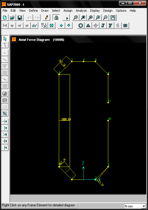
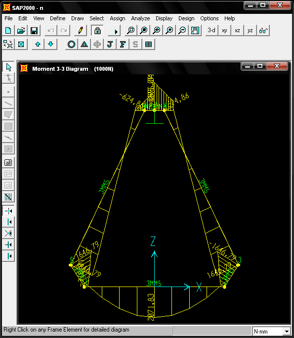
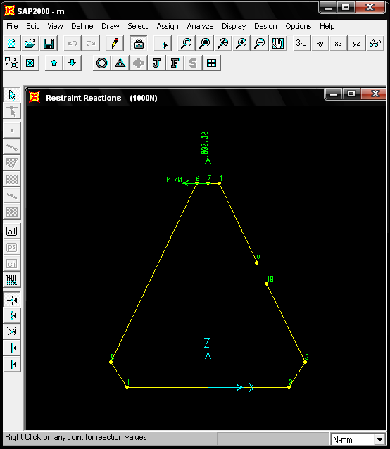
Maillon
oval closed under 1000 N:
Maillon oval open under 1000
N:
Maillon delta closed under
1000 N:
Maillon delta open under 1000
N:
5. Numerical results
MAILLON OVAL 3,5MM CLOSED SAP2000 v7.12 File: O
N-mm Units PAGE 1 9/7/08 15:14:26 S T A T I C L O
A D C A S E S
STATIC
CASE SELF WT
CASE
TYPE FACTOR
1000N
LIVE 0,0000
F R A M E S P A
N D I S T R I B U T E D L O A D S
Load Case 1000N
FRAME TYPE
DIRECTION DISTANCE-A VALUE-A
DISTANCE-B VALUE-B
1 FORCE
GLOBAL-Z 0,0000
-74,0740 1,0000 -74,0740
7 FORCE
GLOBAL-Z 0,0000
-52,3780 1,0000 -52,3780
8 FORCE
GLOBAL-Z 0,0000
-52,3780 1,0000 -52,3780
J O I N T D I S
P L A C E M E N T S JOINT
LOAD
U1
U2
U3
R1
R2 R3
1 1000N
2,088E-05 0,0000
-0,0514 0,0000
2,757E-03 0,0000
2 1000N
-2,088E-05 0,0000
-0,0514 0,0000
-2,757E-03 0,0000
3
1000N
0,0143 0,0000
-0,0362 0,0000
4,083E-03 0,0000
4
1000N
0,0182 0,0000
-0,0296 0,0000
-4,719E-03 0,0000
5
1000N
-0,0143 0,0000
-0,0362 0,0000
-4,083E-03 0,0000
6
1000N
-0,0182 0,0000
-0,0296 0,0000
4,719E-03 0,0000
7 1000N
-2,088E-05 0,0000
-0,0101 0,0000
-4,089E-03 0,0000
8 1000N
2,088E-05 0,0000
-0,0101 0,0000
4,089E-03 0,0000
9
1000N
0,0000
0,0000
0,0000
0,0000
0,0000 0,0000 J O I N T R E A
C T I O N S JOINT
LOAD
F1
F2
F3
M1
M2 M3
9
1000N
0,0000 0,0000
999,9968
0,0000
0,0000 0,0000 F R A M E E L E
M E N T F O R C E S FRAME
LOAD
LOC
P
V2
V3
T
M2 M3
1 1000N
0,00 -12,36
-240,74
0,00
0,00
0,00 988,69
1,63 -12,36
-120,37
0,00
0,00
0,00 1282,09
3,25
-12,36
0,00
0,00
0,00
0,00 1379,89
4,88 -12,36
120,37
0,00
0,00
0,00 1282,09
6,50 -12,36
240,74
0,00
0,00
0,00 988,69
2 1000N
0,00
500,00
12,36
0,00
0,00
0,00 -350,85
12,75
500,00
12,36
0,00
0,00
0,00 -508,41
25,50
500,00
12,36
0,00
0,00
0,00 -665,97
3 1000N
0,00 500,00
-12,36
0,00
0,00
0,00 350,85
12,75
500,00
-12,36
0,00
0,00
0,00 508,41
25,50
500,00
-12,36
0,00
0,00
0,00 665,97
5 1000N
0,00 362,29
344,81
0,00
0,00
0,00 665,97
2,47 362,29
344,81
0,00
0,00
0,00 -187,41
4,95 362,29
344,81
0,00
0,00 0,00
-1040,78
6 1000N
0,00 362,29
-344,81
0,00
0,00 0,00
-1040,78
2,47 362,29
-344,81
0,00
0,00
0,00 -187,41
4,95 362,29
-344,81
0,00
0,00
0,00 665,97
7 1000N
0,00 161,49
178,97
0,00
0,00
0,00 988,69
2,47 253,15
270,63
0,00
0,00
0,00 432,34
4,95 344,81
362,29
0,00
0,00
0,00 -350,85
8 1000N
0,00 161,49
178,97
0,00
0,00
0,00 988,69
2,47 253,15
270,63
0,00
0,00
0,00 432,34
4,95 344,81
362,29
0,00
0,00
0,00 -350,85
9 1000N
0,00
12,36
500,00
0,00
0,00 0,00
-1040,78
8,1E-01
12,36
500,00
0,00
0,00 0,00
-1447,03
1,63
12,36
500,00
0,00
0,00 0,00
-1853,28
2,44
12,36
500,00
0,00
0,00 0,00
-2259,52
3,25
12,36
500,00
0,00
0,00 0,00
-2665,77
10 1000N
0,00 12,36
-500,00
0,00
0,00 0,00
-2665,77
8,1E-01
12,36
-500,00
0,00
0,00 0,00
-2259,52
1,63 12,36
-500,00
0,00
0,00 0,00
-1853,28
2,44 12,36
-500,00
0,00
0,00 0,00
-1447,03
3,25 12,36
-500,00
0,00
0,00 0,00
-1040,78