
LEparagliding development · 3 October 2026
gnuC2: trim, fabric deformation and the next Studio developments
From whole-wing aerodynamic calculations to the shape and loading of individual cells: current work in Studio, OpenCell, flow5 and OpenVSP.
Development update by Francois · For discussion with Pere and the gnuC builder.
Trim angle, calage and wing size
Discussion for Francois, Pere and the first gnuC builder - 3 October 2026
Design decision. First agree the target trim speed for the flying pilot and their equipped mass. Next choose the design angle of attack with sufficient margin toward both stall and accelerated flight. Then solve the required calage and, if necessary, wing size together. The present tables connect these choices: approximately 6° corresponds to 34.4% calage, 8° to 44.3% and 9° to 48.7-48.9%; they do not reproduce 9° trim at 33%.
1 | What has actually been analysed
Fixed size, rigid geometry, no brakes or speedbar. The aerodynamic model uses the current gnuC2 geometry. The reported angle is relative to the centre chord; the supplied wing-angle convention is +0.07°. Pilot mass includes harness and instruments; it is not total flying mass. The stated design starting point is 9° centre-rib angle and 33% calage. The analysis examines whether that combination gives a consistent trim balance for this wing and pilot.
Billow is included; whole-wing aeroelastic deformation is not. The refined flow5 geometry has 121 sections, including intermediate CAD skin sections that represent billow/minirib shaping. The mid-cell profile uses a neighbouring-section approximation to avoid the minirib kink. Separate OpenCell cloth-deformation trials were made, using one held centre cell at 70 Pa and applying its deformation across the span. The engine-table source selects the baseline refined nx40 dataset, not those named cloth trials. Thus these tables should not be described as a fully load-deformed wing.
Span loading and induced flow are aerodynamic outputs. The full-wing panel calculation includes three-dimensional loading and induced effects. What is absent is their iterative feedback into spanwise fabric tension, twist and wing shape. Describe the case as zero imposed sideslip, not “no crossflow physics”: the potential-flow model is three-dimensional, while viscous spanwise flow/separation is limited. Imported rib yaw also differs slightly between geometry routes.
2 | Solver agreement and drag assumptions
Both workflows are automated: flow5 through a custom source/API driver and OpenVSP through scripted API access and VSPAERO. The compared runs show inviscid lift agreement within about 3% for the compared cases after matching section orientation. This is useful cross-code consistency, not proof of equally accurate drag, moments or stall. Comparisons must use matched geometry, mesh, reference quantities and solver versions; the trim comparison uses OpenVSP 3.53.1.
The 241-run tables use flow5 only, with cde = 1.1: fitted refined inviscid loads plus XFoil-based viscous corrections (forced transition at 2%), refined-run offsets and direct 8°/9° anchors. They are engine balance iterations, not 241 new full-wing flow5 solves. OpenVSP provides an independent inviscid comparison with a separate parasite-drag buildup. Inlet corrections were investigated separately; cde = 1.1 must not be relabelled as a validated inlet calculation or combined blindly with another inlet allowance.
3 | What 33%, 8° and scaling mean for the builder
At unchanged size, about 101.2 kg pilot mass produces 36 km/h at approximately 8°, with calage about 44.3%. At 70 kg, the same approximate angle/calage gives 30.2 km/h; at 110 kg it gives 37.5 km/h. Therefore “suited to a heavier pilot at 8° and 36 km/h” is supported conditionally. It does not mean that adding weight to a 33% setup automatically raises its trim angle to 8°: at fixed calage the tables mainly change speed.
For the lighter builder, reducing area could recover 36 km/h after choosing a consistent trim angle/calage. A first estimate at 70 kg and 8° is Snew/Sold ≈ (30.2/36)² = 0.70, or about 0.84 linear scale for geometric similarity. This is only a sizing estimate: scaled wing/line mass, Reynolds number, drag proportions and moment balance all change. Rerun the geometry, aero and engine; scaling alone does not resolve the 33% versus 9° disagreement.
4 | Is 9° the right design angle?
Design assessment: retain 9° as a candidate, not yet as the selected flight trim. At 70 kg the predicted GR improves only from 7.80 at 8° to 7.88 at 9°, while trim speed falls from 30.2 to 28.8 km/h and required calage moves from 44.3% to 48.7%. That small performance gain alone does not justify the higher angle. Compare 8° and 9° at the pilot’s chosen speed, solving scale and calage consistently; retain the approximately 6°/34% case as the current-rigging reference. The available results do not establish which candidate has adequate stall and speedbar margins. Those require brake/accelerator, inlet-pressure and structural-response evidence; a converged high-angle panel result is not a stall boundary.
Engine results | Fixed current wing size
241 engine executions; flow5-derived aero; cde 1.1. Supplied rounded results retained. GR = whole-system glide ratio; sink in m/s. Calage and plumb are distinct chord percentages. Theta follows the LE engine sign convention.
A | Each pilot mass separately trimmed to 36 km/h
| Pilot kg | Centre α° | Calage % | Plumb % | GR | Sink | Theta° |
|---|---|---|---|---|---|---|
| 50.6 | 3.31 | 16.8 | 53.4 | 5.68 | 1.73 | +6.67 |
| 58.1 | 4.00 | 22.0 | 50.2 | 6.21 | 1.59 | +5.15 |
| 65.6 | 4.69 | 26.7 | 47.7 | 6.66 | 1.49 | +3.85 |
| 61.4 | 4.31 | 24.1 | 49.1 | 6.42 | 1.54 | +4.55 |
| 68.9 | 5.00 | 28.6 | 46.8 | 6.84 | 1.45 | +3.32 |
| 76.4 | 5.69 | 32.7 | 44.9 | 7.19 | 1.38 | +2.23 |
| 72.3 | 5.31 | 30.5 | 45.9 | 7.01 | 1.41 | +2.81 |
| 79.8 | 6.01 | 34.4 | 44.1 | 7.32 | 1.35 | +1.78 |
| 87.3 | 6.70 | 38.0 | 42.7 | 7.54 | 1.31 | +0.85 |
| 83.0 | 6.30 | 36.0 | 43.5 | 7.42 | 1.34 | +1.38 |
| 90.5 | 7.00 | 39.5 | 42.1 | 7.63 | 1.30 | +0.47 |
| 98.0 | 7.69 | 42.9 | 40.9 | 7.77 | 1.28 | -0.36 |
| 93.7 | 7.30 | 40.9 | 41.6 | 7.69 | 1.29 | +0.11 |
| 101.2 | 7.99 | 44.3 | 40.4 | 7.82 | 1.27 | -0.71 |
| 108.7 | 8.69 | 47.5 | 39.5 | 7.89 | 1.26 | -1.47 |
B | Fixed mid-case calage; pilot mass ±7.5 kg
Mid pilot masses, in row order: 58.1, 68.9, 79.8, 90.5 and 101.2 kg. Light/mid/heavy entries = speed km/h / sink m/s. Angle stays nearly constant.
| Calage % | Light | Mid | Heavy | Mid α° / GR / sink |
|---|---|---|---|---|
| 22.0 | 33.77 / 1.50 | 35.99 / 1.59 | 38.08 / 1.69 | 4.00 / 6.20 / 1.59 |
| 28.6 | 34.07 / 1.37 | 35.96 / 1.45 | 37.75 / 1.52 | 5.01 / 6.83 / 1.45 |
| 34.4 | 34.35 / 1.29 | 35.98 / 1.36 | 37.55 / 1.42 | 6.01 / 7.31 / 1.36 |
| 39.5 | 34.53 / 1.25 | 35.98 / 1.30 | 37.38 / 1.35 | 7.01 / 7.61 / 1.30 |
| 44.3 | 34.68 / 1.22 | 35.99 / 1.27 | 37.24 / 1.32 | 8.00 / 7.81 / 1.27 |
C | 70 kg versus 110 kg; calage solved at each angle
Paired calage and GR values are 70 / 110 kg. Speed/sink entries use km/h and m/s. Plumb is the supplied representative rounded value.
| α° | Calage % | Plumb % | GR | 70 kg: V / sink | 110 kg: V / sink |
|---|---|---|---|---|---|
| 4 | 22.0 / 22.1 | 50.2 | 6.22 / 6.24 | 39.3 / 1.73 | 48.7 / 2.14 |
| 5 | 28.6 / 28.7 | 46.8 | 6.84 / 6.86 | 36.3 / 1.46 | 44.9 / 1.80 |
| 6 | 34.4 / 34.5 | 44.1 | 7.31 / 7.34 | 33.9 / 1.27 | 42.0 / 1.57 |
| 7 | 39.4 / 39.6 | 42.1 | 7.61 / 7.64 | 31.9 / 1.15 | 39.5 / 1.43 |
| 8 | 44.3 / 44.4 | 40.5 | 7.80 / 7.82 | 30.2 / 1.07 | 37.5 / 1.32 |
| 9 | 48.7 / 48.9 | 39.1 | 7.88 / 7.91 | 28.8 / 1.01 | 35.7 / 1.24 |
| 10* | 53.3 / 53.5 | 37.9 | 7.94 / 7.97 | 27.6 / 0.96 | 34.2 / 1.18 |
* Extrapolated: 10° is beyond the direct flow5 data through 9° used in these tables.
Development gallery and current work
The following supplied screenshots show development experiments and outputs from different runs and versions. They are not all the operating point used for the trim tables. Click any image to open the original at full size.
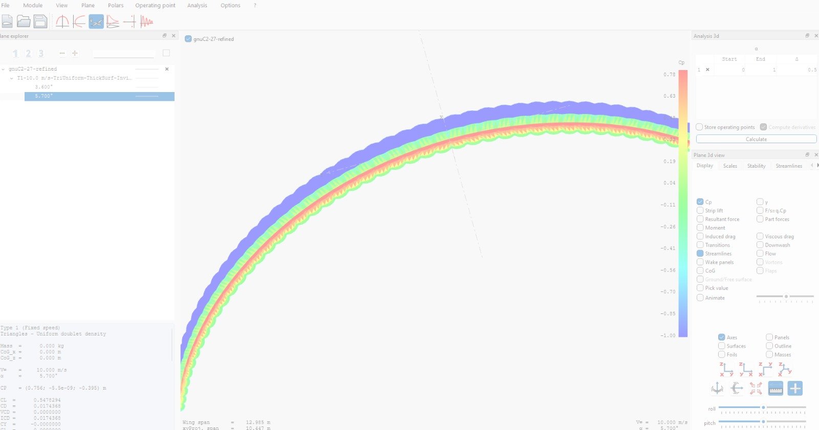
Billowed and deformed profiles in the aero workflow
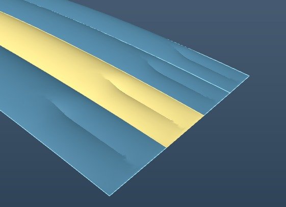
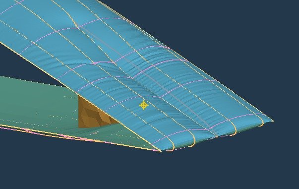
Work now connects Studio geometry, OpenCell deformation studies and the flow5/OpenVSP aerodynamic workflows. CAD billow and profiles extracted from a loaded OpenCell model can be compared as separate geometry cases. This makes it possible to investigate the aerodynamic effect of the shape actually produced by the fabric, rather than relying only on the original rib profile.
The deformed-profile experiments do not retrospectively change the baseline used for the engine tables above. A full spanwise aeroelastic iteration, with local loading changing the structure and the changed structure updating the aerodynamic solution, remains further work.
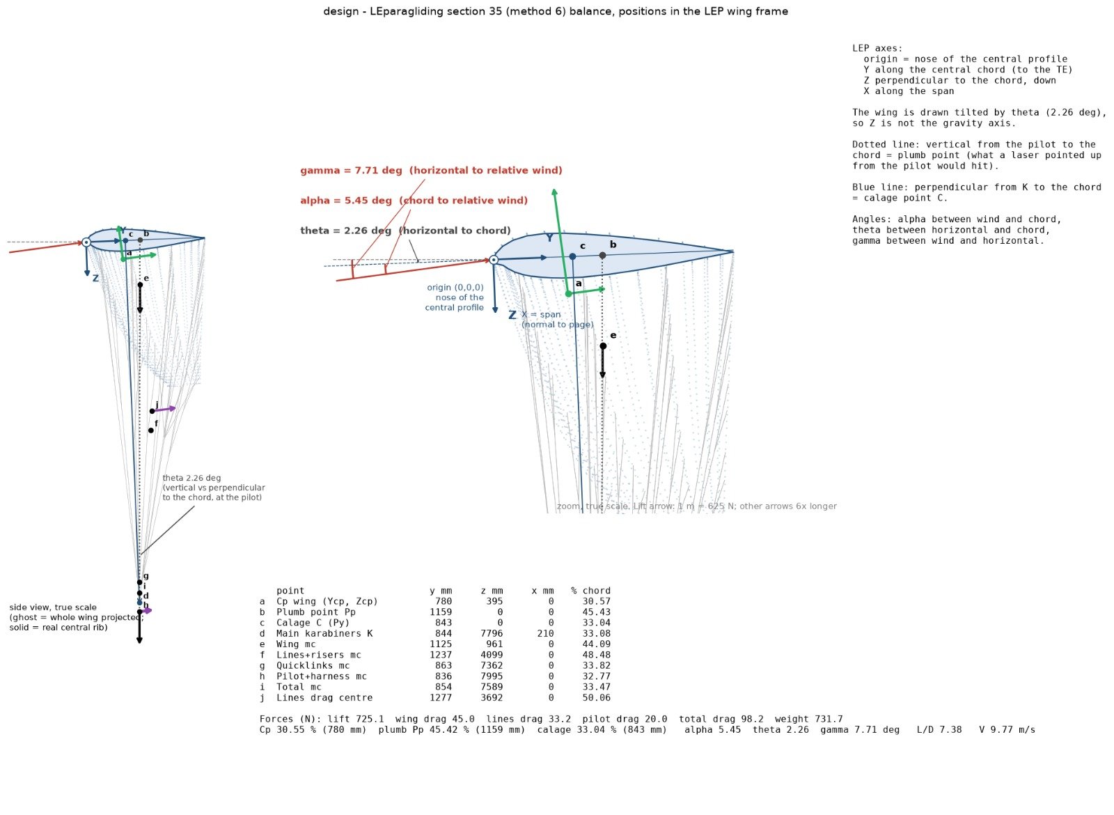
Flight trim display and Method 6
The flight-trim plot in Studio brings the geometry and load balance into one view: centre profile, pilot and carabiners, aerodynamic resultant, line drag, weights, calage, plumb point and flight angles. It uses LEparagliding section 35, Method 6, based on Francois’s closed-form load balance developed in Mathcad about three years ago. Pere’s integration of the layout into LEparagliding DXF output is planned.
The balance is exact for its stated loads and assumptions. The accuracy of predicted flight behaviour still depends on the aerodynamic inputs, geometry and structural assumptions.
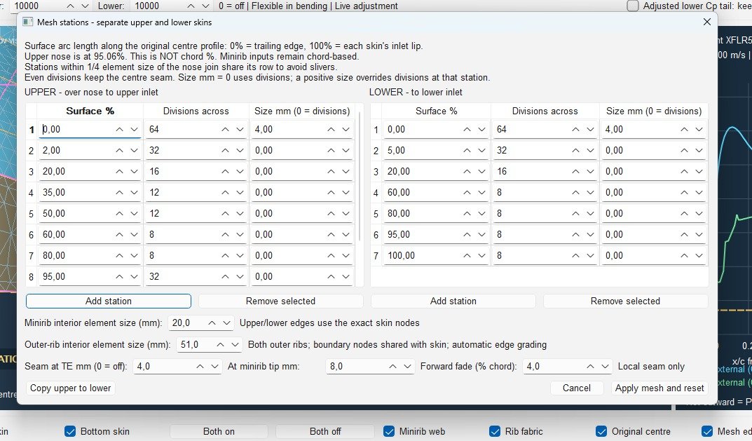
Mesh control, Gmsh and minirib construction
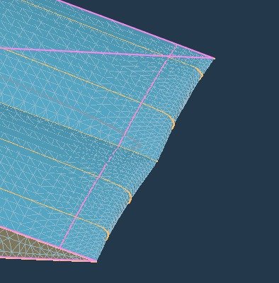
OpenCell provides detailed control of upper- and lower-skin mesh stations, local spacing, rib and minirib element sizes, and refinement near the trailing edge and inlet. Gmsh is now part of the meshing work to obtain suitable triangles. Element shape and refinement matter when interpreting cloth strain and wrinkles; mesh quality is checked alongside resolution sensitivity.
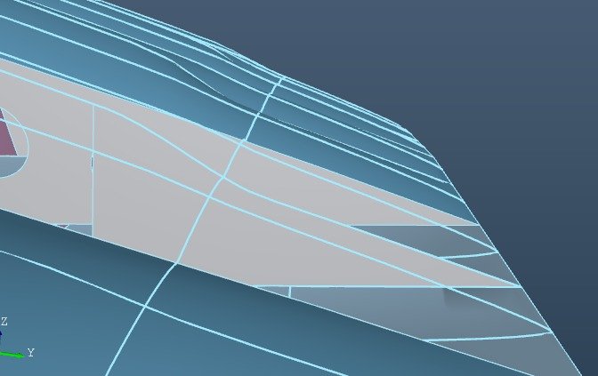
Current development updates the minirib formulation and stitching from the trailing edge. The internal geometry, the surrounding fabric surface and the resulting mesh are inspected together, so that a change in construction can be related to its effect on the deformed profile.
Live sections: seeing how the fabric changes shape
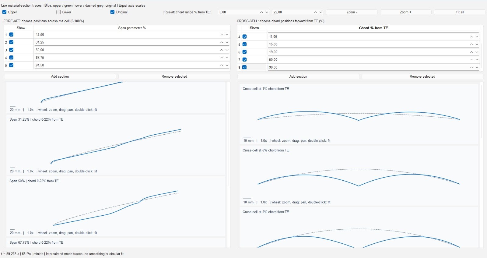
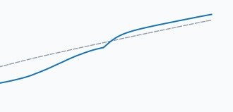
Longitudinal sections at selected positions across a cell and cross-cell traces at selected chord stations show how the skin departs from its original shape. These views are particularly useful around the minirib transition, where a local change can be difficult to interpret in a shaded three-dimensional view. Extracted profiles can then be used in separate aerodynamic comparisons.
Nose and inlet behaviour versus internal pressure
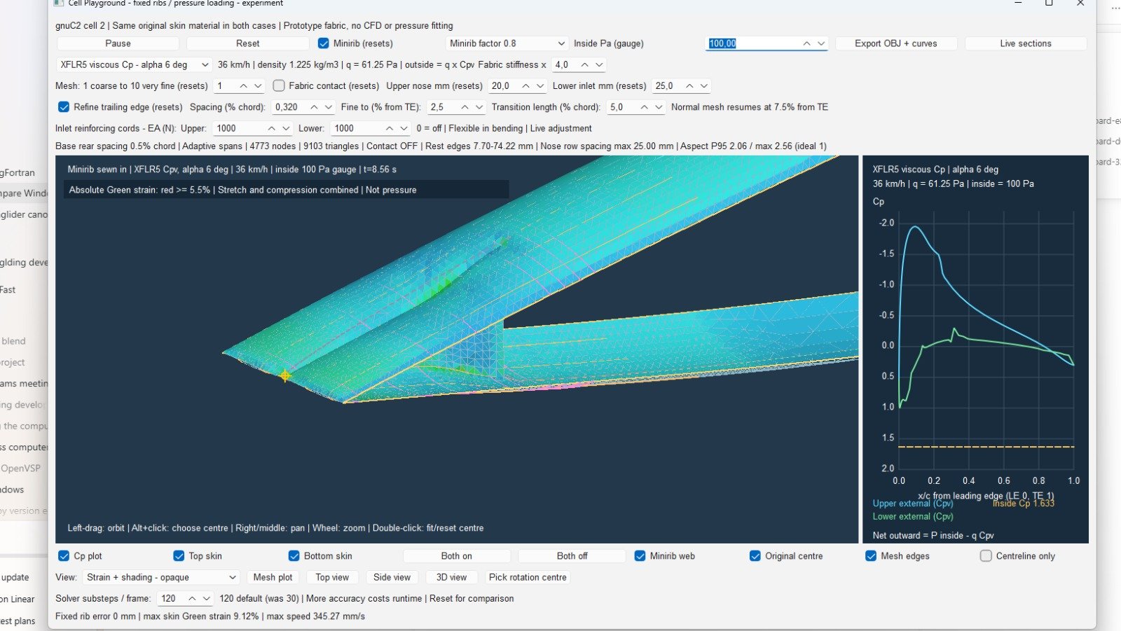
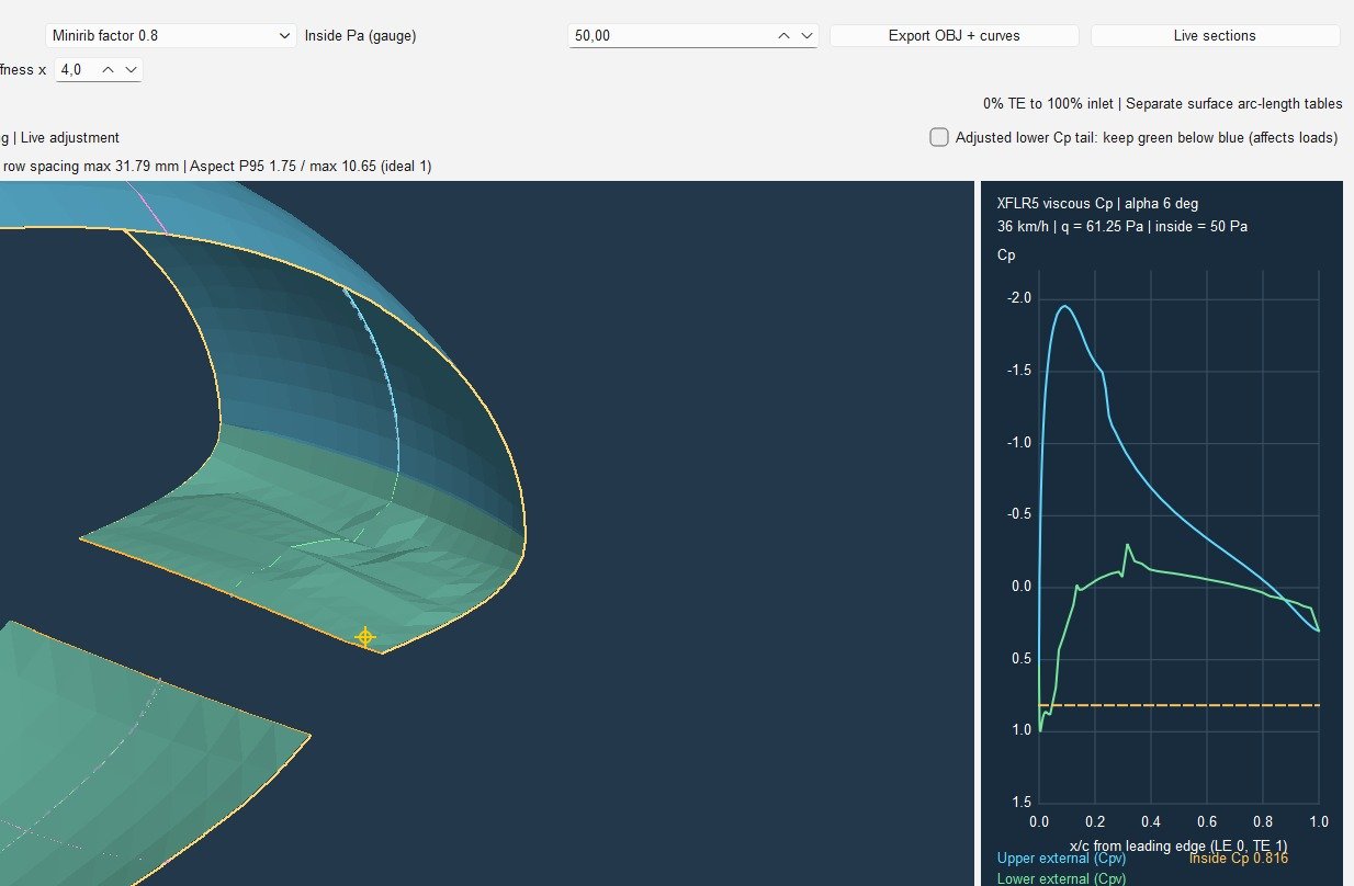
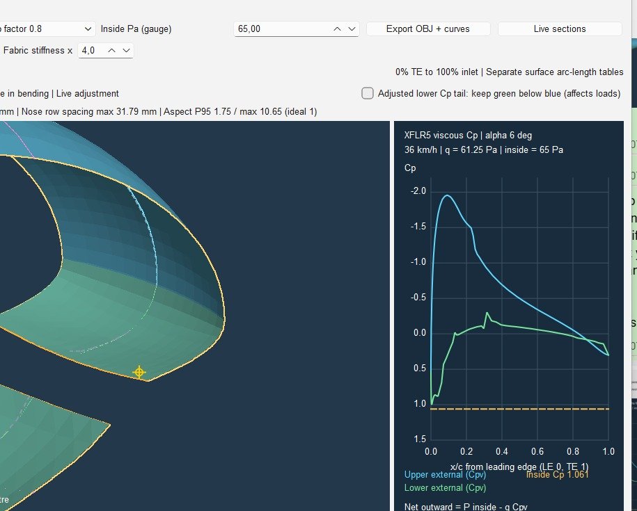
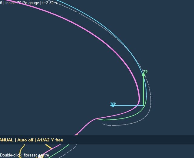
Nose and inlet controls support experiments on the shape response to internal pressure and external pressure loading. The supplied 50 Pa and 65 Pa views illustrate this investigation; the closer 70 Pa view shows the reference and deformed outlines near the inlet. Pressure variation is being used to study local deformation and the onset of collapse, not to claim an established flight limit from these screenshots.
Rib structure, reinforcements and cloth diagnostics
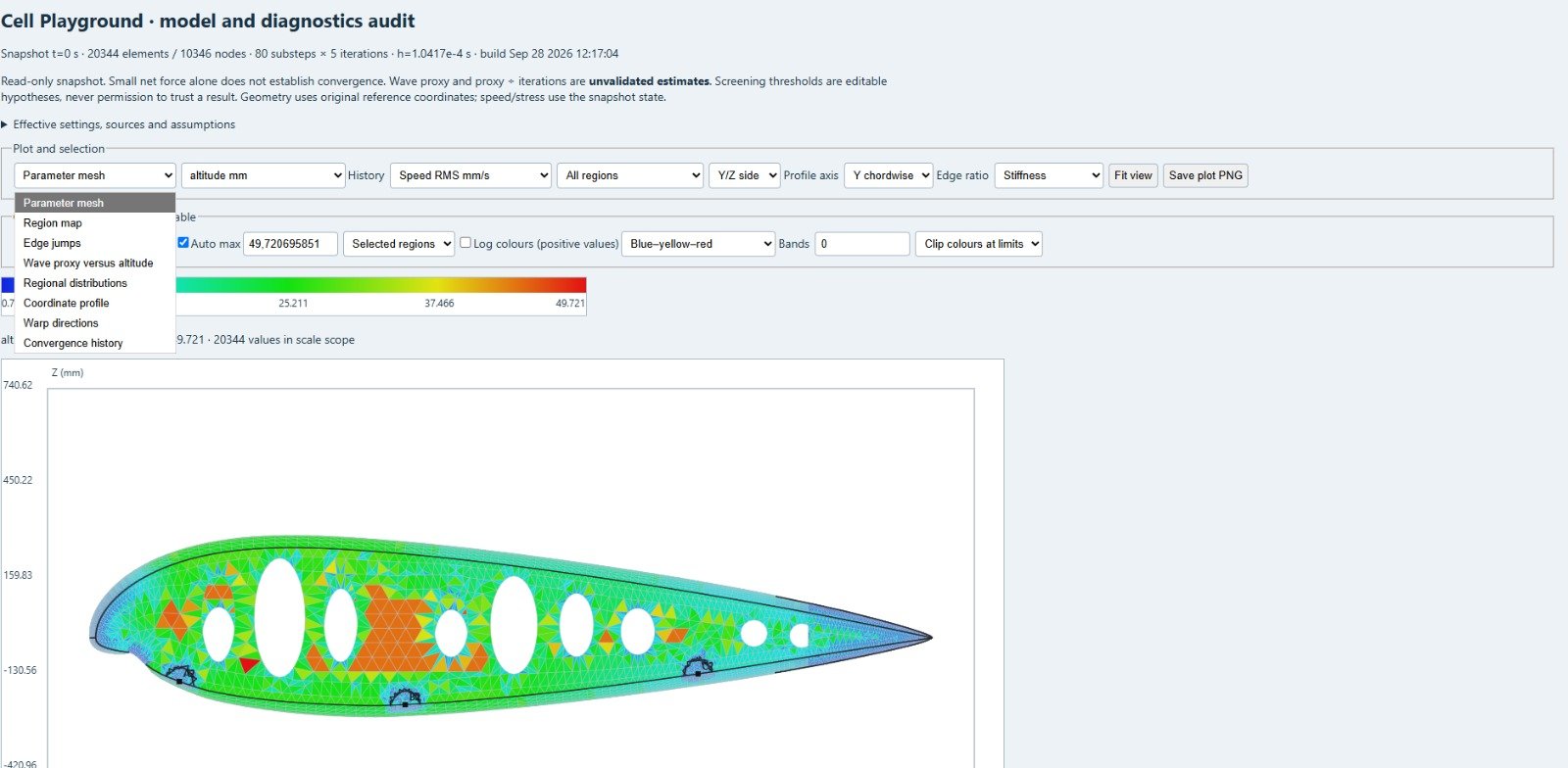
The structural studies include rib deformation and stresses, rods, horizontal and diagonal straps, and added fabric patches. A cloth diagnostics tool helps inspect mesh and material properties, regional distributions, section traces and convergence histories. Plot quantities must be read by their labels: a mesh-quality or element-height plot is not a stress plot.
Line attachment positions, profile deformation and trim
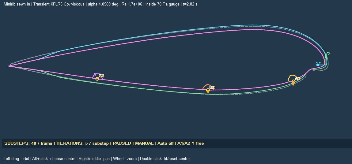
Changing line attachment positions and line settings changes the support supplied to the fabric. OpenCell is used to inspect the resulting profile deformation and line loads, and to examine how these changes affect aerodynamic trim. The staged release applies aero loading with the ribs held, transfers support to the lines with A-Y held, and then releases A-Y while tracking motion and loads.
Next steps toward Studio 0.4.2 on LEparagliding 3.28
- Studio: integrate the flow5/OpenVSP load routes and make it easy to select a small region for OpenCell, initially about five cells or fewer depending on the two-, three- or four-liner arrangement. Select valid cut planes that avoid diagonals; horizontal straps may be cut.
- Full-wing Playground: reconcile applied lift, drag and moments on held geometry, then compare the settled trim of a released model with matched engine cases.
- OpenCell: extend to centre 2.5-cell and off-centre segments. Keep carabiners fixed and line junctions sliding in their assigned planes. Use forced offsets and rotations about rib-plane local Z and the chordline to vary spanwise loading and study where wrinkles appear. Add whole-trailing-edge movement in global Z.
- LEparagliding output: work with Pere to include the Method 6 trim layout in the Fortran-generated DXF output.